SHIFT INTERLOCK
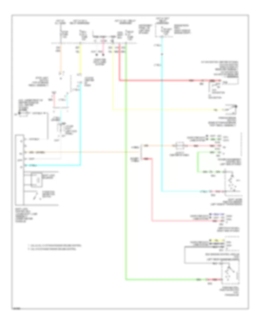
Shift Interlock Wiring Diagram for Toyota Avalon XLE 2014
List of elements for Shift Interlock Wiring Diagram for Toyota Avalon XLE 2014:
- (2.5l: under front of center console) (3.5l: center of dash) j/c d96
- (or red)
- (w/ navigation: center of dash)
- (w/o navigation) radio & display receiver assembly (w/ navigation) navigation receiver assembly
- 2.5l & 3.5l w/ dynamic radar cruise control
- 3.5l w/o dynamic radar cruise control
- A16
- A46
- A54
- B10
- B27
- Ba2
- Ba3
- Bkup lp fuse 7.5a
- Ca1h
- Ca1l
- Can+
- Can-
- Canh
- Canl
- Certification ecu (right end of dash)
- Computer data lines system
- D104
- D105
- D20
- D30
- D32
- D64
- D71
- De2
- E19
- Ecm (engine control module) (3.5l) (left rear of engine compt)
- Ecu- ig1 2 fuse 10a
- Engine room r/b 2 (right side of engine compt)
- Except hybrid
- Hot at all times
- Hot w/ ig1 1 relay energized
- Hot w/ ig1 2 relay energized
- Hot w/ igct relay energized
- Hybrid
- Instrument panel j/b (left end of dash)
- J/c a46 & d71 (left kick panel)
- J/c d100 (center of dash)
- J/c d117 (center of dash)
- Main body ecu
- Out
- P position detection switch
- Park/neutral position switch (3.5l) (transaxle)
- Parking brake switch (base of parking brake foot pedal assembly)
- Pkb
- Pm igct fuse 7.5a
- Pnk
- Power management control ecu (left end of dash)
- Red
- Shift lever position sensor (left side of transmission)
- Shift lock control ecu (lower shift liver assembly) (under center console)
- Shift lock solenoid
- Stop fuse 7.5a
- Stop light switch (top of brake pedal assembly)
- Stp
- W/ navigation
- W/o navigation
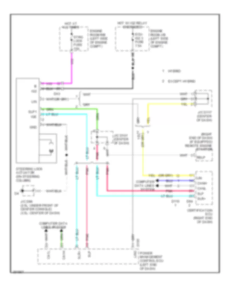
Steering Column Wiring Diagram for Toyota Avalon XLE 2014
List of elements for Steering Column Wiring Diagram for Toyota Avalon XLE 2014:
- (right end of dash) (if equipped) remote engine starter
- Ca1h
- Ca1l
- Canh
- Canl
- Certification ecu (right end of dash)
- Computer data lines system
- D105
- D110
- D64
- Da3
- Ecu- ig2 3 fuse 7.5a
- Engine room j/b (left side of engine compt)
- Engine room r/b (left side of engine compt)
- Except hybrid
- Gnd
- Hot at all times
- Hot w/ ig2 relay energized
- Hybrid
- Ig2
- Ige
- J/c d101 (center of dash)
- J/c d117 (center of dash)
- J/c d96 (2.5l: under front of center console) (3.5l: center of dash)
- Lin
- Lin2
- Pnk
- Power management control ecu (left end of dash)
- Rslp
- Slp
- Slp1
- Slr+
- Steering lock actuator (on steering column)
- Strg lock fuse 10a
 Deutsch
 English
 English
 Español
 Français
 Nederlands
 Русский


