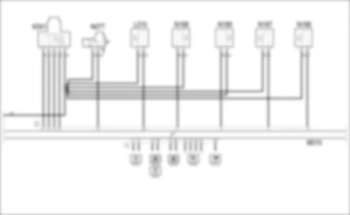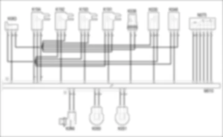

WIRING DIAGRAM - PETROL ENGINES ELECTRONIC MANAGEMENT - Alfa Romeo 159 3.2 JTS Fino a 12/05
COMPONENTS - PETROL ENGINES ELECTRONIC MANAGEMENT - Alfa Romeo 159 3.2 JTS Fino a 12/05
| Component code | Description | Reference to the operation |
| A030 | IGNITION COIL | |
| B001 | JUNCTION UNIT | |
| B002 | JUNCTION UNIT UNDER DASHBOARD | |
| B099 | MAXIFUSE BOX ON BATTERY | |
| C010 | LEFT FRONT EARTH | - |
| C015 | DASHBOARD EARTH, DRIVER'S SIDE | - |
| C020 | PASSENGER SIDE DASHBOARD EARTH | - |
| C040 | ENGINE EARTH | - |
| D001 | FRONT/DASHBOARD COUPLING | - |
| D004 | FRONT/ENGINE COUPLING | - |
| E050 | INSTRUMENT PANEL | |
| I030 | BRAKE PEDAL SWITCH | |
| I031 | CLUTCH PEDAL SWITCH | |
| I050 | INERTIA SWITCH | |
| K015 | LAMBDA SENSOR ON PRE-CATALYZER | |
| K016 | LAMBDA SENSOR ON PRE-CATALYZER -2 | |
| K017 | LAMBDA SENSOR ON CATALYZER | |
| K018 | LAMBDA SENSOR ON CATALYZER - 2 | |
| K030 | LOW ENGINE OIL PRESSURE SENSOR (SWITCH) | |
| K036 | ENGINE COOLANT TEMPERATURE SENSOR/SENDER UNIT | |
| K041 | AIR FLOW METER | |
| K046 | RPM SENSOR | |
| K048 | ABSOLUTE PRESSURE SENSOR | |
| K050 | DETONATION SENSOR | |
| K051 | DETONATION SENSOR - 2 | |
| K055 | ACCELERATOR PEDAL POTENTIOMETER | |
| K083 | FUEL PRESSURE SENSOR | |
| K191 | RIGHT HEAD INLET SIDE TIMING SENSOR | |
| K192 | RIGHT HEAD EXHAUST SIDE TIMING SENSOR | |
| K193 | LEFT HEAD INLET SIDE TIMING SENSOR | |
| K194 | LEFT HEAD EXHAUST SIDE TIMING SENSOR | |
| L010 | FUEL VAPOUR RECOVERY SOLENOID VALVE | |
| L065 | FUEL SHUT-OFF SOLENOID VALVE | |
| M001 | BODY COMPUTER | |
| M010 | ENGINE MANAGEMENT ECU | |
| M089 | STEERING LOCK CONTROL UNIT (NBS) | |
| N040 | FUEL PUMP AND LEVEL GAUGE | |
| N070 | INJECTOR | |
| N075 | THROTTLE BODY ACTUATOR | |
| N077 | FUEL PRESSURE REGULATOR | |
| N186 | INLET SIDE PHASE TRANSFORMER SOLENOID - RIGHT HEAD | |
| N187 | EXHAUST SIDE PHASE TRANSFORMER SOLENOID - RIGHT HEAD | |
| N188 | INLET SIDE PHASE TRANSFORMER SOLENOID - LEFT HEAD | |
| N189 | EXHAUST SIDE PHASE TRANSFORMER SOLENOID - LEFT HEAD |
COMPONENT LOCATION - PETROL ENGINES ELECTRONIC MANAGEMENT - Alfa Romeo 159 3.2 JTS Fino a 12/05
| Component code | Description | Reference to the operation |
| A030 | IGNITION COIL | |
| B001 | JUNCTION UNIT | |
| B002 | JUNCTION UNIT UNDER DASHBOARD | |
| B099 | MAXIFUSE BOX ON BATTERY | |
| C010 | LEFT FRONT EARTH | - |
| C015 | DASHBOARD EARTH, DRIVER'S SIDE | - |
| C020 | PASSENGER SIDE DASHBOARD EARTH | - |
| C040 | ENGINE EARTH | - |
| D001 | FRONT/DASHBOARD COUPLING | - |
| D004 | FRONT/ENGINE COUPLING | - |
| E050 | INSTRUMENT PANEL | |
| I030 | BRAKE PEDAL SWITCH | |
| I031 | CLUTCH PEDAL SWITCH | |
| I050 | INERTIA SWITCH | |
| K015 | LAMBDA SENSOR ON PRE-CATALYZER | |
| K016 | LAMBDA SENSOR ON PRE-CATALYZER -2 | |
| K017 | LAMBDA SENSOR ON CATALYZER | |
| K018 | LAMBDA SENSOR ON CATALYZER - 2 | |
| K030 | LOW ENGINE OIL PRESSURE SENSOR (SWITCH) | |
| K036 | ENGINE COOLANT TEMPERATURE SENSOR/SENDER UNIT | |
| K041 | AIR FLOW METER | |
| K046 | RPM SENSOR | |
| K048 | ABSOLUTE PRESSURE SENSOR | |
| K050 | DETONATION SENSOR | |
| K051 | DETONATION SENSOR - 2 | |
| K055 | ACCELERATOR PEDAL POTENTIOMETER | |
| K083 | FUEL PRESSURE SENSOR | |
| K191 | RIGHT HEAD INLET SIDE TIMING SENSOR | |
| K192 | RIGHT HEAD EXHAUST SIDE TIMING SENSOR | |
| K193 | LEFT HEAD INLET SIDE TIMING SENSOR | |
| K194 | LEFT HEAD EXHAUST SIDE TIMING SENSOR | |
| L010 | FUEL VAPOUR RECOVERY SOLENOID VALVE | |
| L065 | FUEL SHUT-OFF SOLENOID VALVE | |
| M001 | BODY COMPUTER | |
| M010 | ENGINE MANAGEMENT ECU | |
| M089 | STEERING LOCK CONTROL UNIT (NBS) | |
| N040 | FUEL PUMP AND LEVEL GAUGE | |
| N070 | INJECTOR | |
| N075 | THROTTLE BODY ACTUATOR | |
| N077 | FUEL PRESSURE REGULATOR | |
| N186 | INLET SIDE PHASE TRANSFORMER SOLENOID - RIGHT HEAD | |
| N187 | EXHAUST SIDE PHASE TRANSFORMER SOLENOID - RIGHT HEAD | |
| N188 | INLET SIDE PHASE TRANSFORMER SOLENOID - LEFT HEAD | |
| N189 | EXHAUST SIDE PHASE TRANSFORMER SOLENOID - LEFT HEAD |
DESCRIPTION - PETROL ENGINES ELECTRONIC MANAGEMENT - Alfa Romeo 159 3.2 JTS Fino a 12/05
The JTS engine features a fuel supply system with a high pressure pump for direct injection.An electronic control system supervises and governs all engine parameters to optimise performance and fuel consumption by means of a real-time response to different service conditions.The system is managed by a BOSCH MED7.6.1 control unit with a motorized throttle that controls both the ignition and the phased, sequential injection.Depending on the signals received from numerous sensors, the control unit controls the injectors connected to it managing the following systems:- fuel supply;- high pressure fuel pump control;- air supply;- accelerator pedal- engine cooling;- exhaust with catalytic converters controlled by four Lambda sensors;- fuel vapour recirculation.The control unit of this JTS engine manages the operation of the high pressure fuel pump by controlling an electric pressure regulator and an associated pressure sensor.The throttle body is also controlled electronically by the control unit: throttle opening is calculated in accordance with specific software mapped inside the engine control unit. This system does away with the need for a mechanical link between accelerator pedal and throttle body.The control unit controls the engine timing by means of a pair of electrohydraulic phase transformers - one on the inlet shaft and one on the exhaust shaft - for each bank; this solution makes it possible to ensure optimum timing managing the inlet and the exhaust separately; four timing sensors allows the continuous control of the solution set.The fuel shut-off solenoid valve, which cuts off the return flow of fuel to the tank is located on the fuel return pipe to the tank; this solenoid valve - only operated with the engine started - has the function of preventing the high pressure pump from draining thereby facilitating engine starting.Thanks to the electronic management described above, this engine conforms to the most recent pollution control standards (EURO 4).For more detailsThe system is also controlled by dedicated relays in the engine compartment control unit. Lines supplying the control unit and various system components (sensors and actuators) are protected by dedicated fuses that are also located inside the engine compartment.
FUNCTIONAL DESCRIPTION - PETROL ENGINES ELECTRONIC MANAGEMENT - Alfa Romeo 159 3.2 JTS Fino a 12/05
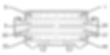
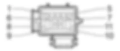
Engine management control unit M10 controls and governs the entire electronic ignition and injection system.The control unit M10 receives a direct supply from the battery at pin 92 of connector A via the line protected by fuse F18 of junction unit B1.The ignition-operated power supply (15/54) arrives via a line protected by fuse F16 of the engine compartment junction unit B1 at pin 67 of connector A of M10 .Pins 1, 2 and 4 of connector A of M10 are earthed.Main injection relay T9 of B1 controls the entire system: it is energized by an earth signal from pin 25 of connector A of engine control unit M10 and then forwards a power supply:- to pins 3, 5 and 6 of connector A of the actual control unit, via the line protected by fuse F22 of B1;- to the air flow meter K41, to the fuel vapour recovery solenoid valve L10, to the phase transformers N188, N189, N187 and N186 and to the Lambda sensors K15, K16, K17 and K18 and lastly to the high pressure pump N77; (all these lines are protected by fuse F11 of B1);- to the coils A30 and to the fuel shut-off solenoid valve L65, via the line protected by fuse F17 of B1.Fuel pump relay T10 of B1 is supplied by the line protected by fuse F21 of B1.It is energized by a control signal coming from pin 8 of connector A of control unit M10 and provides the power supply for the electric fuel pump N40 which is earthed via the inertia switch I50 which interrupts the circuit in the case of an impact and stops the dangerous supply of fuel.The engine management control unit M10 receives signals from the various sensors thereby keeping all the engine operating parameters under control.The rpm sensor K46 provides information, via a frequency signal sent to pins 51 and 36 of connector B of the control unit M10, about the engine speed.The right head intake side timing sensor K191 receives a power supply form pin 26 of connector B of control unit M10 and a reference earth from pin 7 of connector B and sends a frequency signal corresponding to the timing to pin 52 of connector B of the actual control unit.The left head intake side timing sensor K193 receives a power supply form pin 26 of connector B of control unit M10 and a reference earth from pin 7 of connector B and sends a frequency signal corresponding to the timing to pin 53 of connector B of the actual control unit.The right head exhaust side timing sensor K192 receives a power supply form pin 26 of connector B of control unit M10 and a reference earth from pin 7 of connector B and sends a frequency signal corresponding to the timing to pin 37 of connector B of the actual control unit.The left head exhaust side timing sensor K194 receives a power supply form pin 26 of connector B of control unit M10 and a reference earth from pin 7 of connector B and sends a frequency signal corresponding to the timing to pin 38 of connector B of the actual control unit.The fuel pressure sensor K83 receives a power supply form pin 26 of connector B of control unit M10 and a reference earth from pin 7 of connector B and sends a frequency signal corresponding to the fuel pressure to pin 8 of connector B of the actual control unit.The engine temperature sender unit K36 receives a reference earth from pin 7 of connector B of the control unit M10 and provides a signal proportional to the temperature of the engine coolant at pin 22 of connector B of the control unit.The four Lambda sensors K15, K16, K17 and K18 provide the control unit M10 with information surrounding the correct composition of the air/fuel mixture in different exhaust positions: two - linear type - are located upstream of the preconverters while two flat sensors are located downstream of the preconverters.The linear sensor K15 sends the signals to pins 55, 56, 77 and 78 of connector A of M10, whilst it is heated by a resistance to ensure correct operation even when cold. The resistance is supplied by fuse F11 of B1 and receives an earth signal from pin 73 of connector A of control unit M10.The linear sensor K16 sends the signals to pins 57, 58, 79 and 80 of connector A of M10, whilst it is heated by a resistance to ensure correct operation even when cold. The resistance is supplied by fuse F11 of B1 and receives an earth signal from pin 51 of connector A of control unit M10.The planar sensor K17, sends the signals to pins 74 and 75 of connector A of M10 whilst it is heated by a resistance supplied by fuse F11 of B1 and receives an earth signal from pin 50 of connector A of control unit M10.The planar sensor K18 sends the signal to pins 52 and 53 of connector A of M10 whilst it is heated by a resistance supplied by fuse F11 of B1 and receives an earth signal from pin 94 of connector A of control unit M10.The detonation sensor K50 makes it possible to have information about detonation conditions by means of a frequency signal sent to pin 44 of connector B of control unit M10: it receives a reference earth from pin 59 of connector B.The detonation sensor K51 makes it possible to have information about detonation conditions by means of a frequency signal sent to pin 58 of connector B of control unit M10: it receives a reference earth from pin 43 of connector B.The air flow meter K41 (supplied by fuse F11 of B1) is connected to pins 11, 12, 13 and 27 of connector B of control unit M10.The accelerator pedal K55 has two built in potentiometers (one main one and one safety one). The first receives the power supply and earth respectively from pins 83 and 81 of connector A of M10 and sends the corresponding signal to pin 82 of 59 and 61 of connector A of M10 and sends the signal to pin 60 of the same connector.The minimum engine oil pressure sensor K30 receives a power supply form pin 26 of connector B of control unit M10 and a reference earth from pin 7 of connector B and sends a minimum oil pressure signal to pin 28 of connector B of the same control unit.The absolute pressure sensor K48 receives a power supply form pin 26 of connector B of control unit M10 and a reference earth from pin 7 of connector B and sends a signal proportional to the pressure in the intake chamber to pin 23 of connector B of the same control unit.Pin 14 of connector A of M10 receives the signal coming from the brake lights switch I30 - N.A. contact - with an ignition-controlled supply (INT) from fuse F37 of junction unit B2; it receives the signal - N.C. contact - coming from the brake lights switch I30 at pin 20 of connector A of M10 with an ignition-controlled supply (INT) from fuse F35 of junction unit B2.Pin 32 of connector A of M10 receives the signal coming from the clutch switch I31.The control unit M10 controls the opening of the individual injectors N70, through the special signals sent from pins 47 and 48 (cyl. 1), 32 and 33 (cyl. 2), 18 and 17 (cyl. 3), 49 and 50 (cyl.4), 34 and 35 (cyl. 5) and lastly 19 and 20 (cyl.6) of connector B of M10.The fuel pressure regulator N77 (supplied by fuse F11 of B1) is operated by the control unit M10 by pin 31 of connector B.The fuel shut-off solenoid valve L65 (supplied by fuse F17 of B1) is operated by the control unit M10 by pin 60 of connector B.The control unit M10 also controls the six coils A30 (supplied by fuse F17 of B1) by means of control (earth) signals for the primary coil windings from pin 1 of connector B of M1 - right bank - and from pin 16 of connector B of M1 - left bank, whilst the secondary winding sends the impulse to the spark plugs: from pins 54, 56 and 40 of connector B of M10 for cylinders 1, 3 and 5 and from pins 55, 53 and 41 of connector B of M10 for cylinders 2, 4 and 6 respectively.The throttle body actuator N75 has two built in potentiometers connected in parallel: this controls the throttle opening by means of a stepping motor.The motor receives a power supply from pins 15 and 30 of connector B of M10. Pin 24 of connector B sends the power supply to the two potentiometers, pin 9 provides the earth signal for them, whils pins 10 and 25 of the same connector receive signals that arrive from the throttle body actuator N75.The fuel vapour recovery solenoid valve L10 allows the flow of fuel vapours to the engine intake where they are added to the mixture entering the combustion chamber. The valve L10 (supplied by fuse F11 of B1) is opened by the control unit when the engine is in load conditions by means of a duty cycle type signal from pin 46 of connector B of M10.The inlet side phase transformer - right head - N186 mechanically controls the timing advance at the intake: supplied by fuse F11 of B1, it is controlled by pin 3 of connector B of the control unit.The exhaust side phase transformer - right head - N187 mechanically controls the timing advance at the exhaust: supplied by fuse F11 of B1, it is controlled by pin 2 of connector B of the control unit.The inlet side phase transformer - left head - N188 mechanically controls the timing advance at the intake: supplied by fuse F11 of B1, it is controlled by pin 5 of connector B of the control unit.The exhaust side phase transformer - left head - N189 mechanically controls the timing advance at the exhaust: supplied by fuse F11 of B1, it is controlled by pin 4 of connector B of the control unit.The control unit M10 is then connected via the CAN to the Body Computer M1 and to the other network nodes: information on the following is sent through this connection- system autodiagnosis, that can be used by connecting to connector C of M1: signals arrive from pin 87 of connector A from the control unit M10 via the special diagnostic line;- engine coolant temperature, which is sent to the instrument panel E50 which manages the gauge and the warning light;- engine rpm, which is sent to the instrument panel E50 rev counter;- minimum engine oil pressure, which is sent to the instrument panel E50 which manages the warning light;It receives the speedometer signal, via the CAN, produced by the ABS control unit M50.The autodiagnostic system for the control unit M10 also produces a signal - which leaves pin 68 of connector A - which is connected directly to the EOBD warning light in the instrument panel E50.
 Deutsch
 English
 English
 Español
 Français
 Nederlands
 Русский


