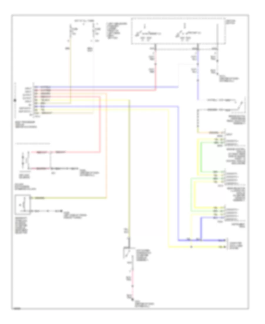
SHIFT INTERLOCKS
Shift Interlock Wiring Diagram for Jaguar XJR 2002
List of elements for Shift Interlock Wiring Diagram for Jaguar XJR 2002:
- (0) off
- Acc (i)
- B+
- Body processor module (behind glove box)
- Brake switch (near brake pedal mounting assembly)
- Ca1
- Can data +
- Can data -
- Cc14
- Cc2r (left side of trans- mission tunnel)
- Cc3l (center of dash, on firewall)
- Column switchgear (steering column)
- Computer data lines system
- Em82
- Em83
- Engine control module (at right rear side of engine compt, in control module enclosure)
- Fc14
- Fc17l (center of dash, on firewall)
- Fc24
- Fc29l (center of dash, on firewall)
- Fuse 15a
- Gear selector illumination module (in center console assembly)
- Gearshift interlock solenoid (in center console, near gear selector)
- Hot at all times
- Ignition switch
- Input
- Instrument pack
- Keylock solenoid
- Left heelboard fuse box (under front of left rear seat bottom)
- Nca
- Not-in-park microswitch (in center console assembly)
- Output
- Run (ii)
- Sc1
- Scp data +
- Scp data -
- Start (iii)
 Čeština
 Dansk
Dansk Ελληνικά
 English
 English
 Español
 Suomi
Suomi Français
 Français
 עברית
עברית Hrvatski
 Magyar
 Italiano
 日本語
日本語 한국어
한국어 Nederlands
 Polski
 Português
 Português
 Română
 Русский
 Slovenčina
 Slovenščina
 Svenska
 Türkçe
 中文 (中国)
 Deutsch