ELECTRONIC POWER STEERING
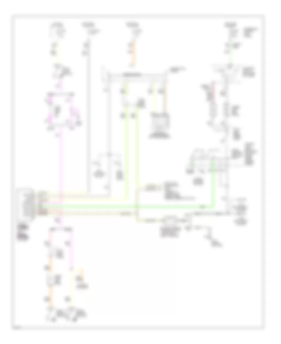
Electronic Power Steering Wiring Diagram for Infiniti J30 t 1997
List of elements for Electronic Power Steering Wiring Diagram for Infiniti J30 t 1997:
- (1996-97) (1995)
- (left front
- (left rear wheel- well)
- (left side of i/p)
- (right front
- (right side of i/p)
- 1996-
- 1996-97
- 2-1
- A25 c1
- A26 c2
- A39 d11
- All times
- Combination meter
- Cruise control system
- Data link connector for consult (under left side of dash, under steering column)
- Diode (left side of i/p)
- Diodes (left kick panel)
- Fender)
- Fuse 15a
- Fuse 32 7.5a
- Fuse 7.5
- Fuse 7.5a
- Fuse block (on left kick panel)
- Fusible link, fuse & relay box (in left front inner fender panel)
- G100
- G101
- G111 (near battery)
- G15 t8
- G201
- G202
- Gnd
- Hot at
- Hot in on
- Hot in on or start
- Ign sw
- Inhibit
- Inhibitor switch (left side of trans)
- J/c 12
- J/c 6 (left side of i/p)
- J/c 7 (left side of i/p)
- Or start
- Park brake switch
- Park/ neutral position relay
- Pb sw
- Power steering solenoid valve
- Power steering steering steering steering control unit (behind (behind (behind (behind left side left side left side left side of dash)
- Ps sol
- Side of engine)
- Speedometer
- Stop lamp
- Stop lamp switch
- Stp sw
- V sens
- Vehicle speed sensor (on transmission)
- Warning systems
 Čeština
 Dansk
Dansk Ελληνικά
 English
 English
 Español
 Suomi
Suomi Français
 Français
 עברית
עברית Hrvatski
 Magyar
 Italiano
 日本語
日本語 한국어
한국어 Nederlands
 Polski
 Português
 Português
 Română
 Русский
 Slovenčina
 Slovenščina
 Svenska
 Türkçe
 中文 (中国)
 Deutsch