TRANSMISSION
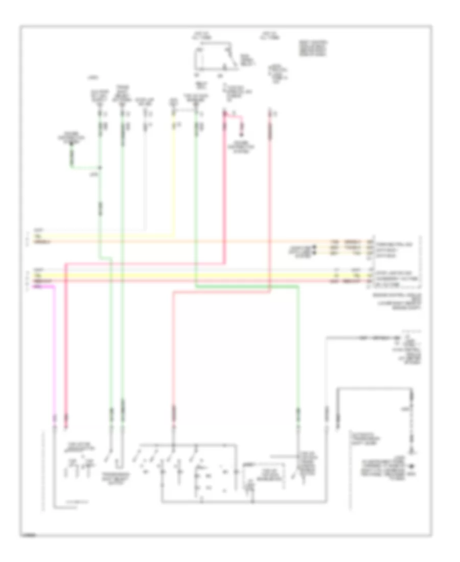
Transmission Wiring Diagram (1 of 2) for Cadillac XLR 2008
 https://portal-diagnostov.com/license.html
Automotive Electricians Portal FZCO
Automotive Electricians Portal FZCO
https://portal-diagnostov.com/license.html
https://portal-diagnostov.com/license.html
Automotive Electricians Portal FZCO
Automotive Electricians Portal FZCO
List of elements for Transmission Wiring Diagram (1 of 2) for Cadillac XLR 2008:
- Acc/tcm fuse 3 10a
- Accessory voltage
- Automatic transmission
- Automatic transmission input shaft speed (iss) sensor
- Automatic transmission internal mode switch (ims)
- Automatic transmission output shaft speed (oss) sensor
- Battery pos volt
- Computer data lines system
- D11
- Data bus +
- Data bus -
- Driver information center (dic)
- E11
- Ecm/tcm fuse 11 15a
- G106
- Gmlan (ecm)
- Ground
- Heads up display (hud) (top left side of dash)
- Hot at all times
- Hot in run or start
- Hud class 2 serial data
- Hud message center
- Ignition 1 voltage
- Instrument panel cluster (ipc)
- Ipc class 2 serial data
- Iss signal
- Jx106 (in engine harness, right rear of engine compt by battery, grounded to g106)
- Logic
- Oss signal
- Park/neutral sig
- Pnk
- Power distribution system
- Range signal a
- Range signal b
- Range signal c
- Range signal p
- Red
- Stop lamp sw sig
- Tan
- Tap up/dn sw sig
- Transmission control module (tcm)
- Underhood fuse block (right rear of engine compt)
- Up-shift ind
Transmission Wiring Diagram (2 of 2) for Cadillac XLR 2008
List of elements for Transmission Wiring Diagram (2 of 2) for Cadillac XLR 2008:
- Acc volt
- Accessory voltage
- Automatic transmission shift lever
- B+ voltage
- Body control module (bcm) (behind right side of dash)
- Btsi sol/col lock fuse 10 10a
- Computer data lines system
- Data bus +
- Data bus -
- Engine control module (ecm) (lower right rear of engine compt)
- G202
- Hot at all times
- Hvac control module (at center of dash)
- I/p lamp ctrl
- J246
- J276
- Jx202 (in instrument panel harness, at base of right a pillar behind trim panel, grounded to g202)
- Logic
- Park/neutral sig
- Pnk
- Power distribution system
- Relay cntl
- Run/ crank relay 7
- Stop lamp sw sig
- Stop lmp sw sig
- Tan
- Tap dwn -
- Tap up +
- Tap up/ dwn enabled sig
- Tap up/ tap dwn enabled sig
- Tap up/ tap dwn trans- mission enable switch
- Tap up/tap down switch
- Trans shift select sw (park) sig
- Transmission shift select switch
- Tutd sw strg col sw fuse 28 2a

 Čeština
 Dansk
Dansk Ελληνικά
 English
 English
 Español
 Suomi
Suomi Français
 Français
 עברית
עברית Hrvatski
 Magyar
 Italiano
 日本語
日本語 한국어
한국어 Nederlands
 Polski
 Português
 Português
 Română
 Русский
 Slovenčina
 Slovenščina
 Svenska
 Türkçe
 中文 (中国)