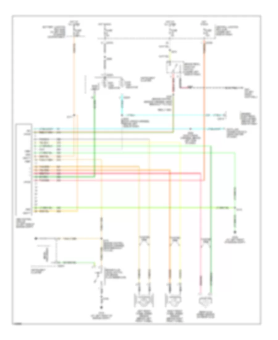
ANTI-LOCK BRAKES
Anti-lock Brakes Wiring Diagram for Ford Pickup Heritage F150 2004
List of elements for Anti-lock Brakes Wiring Diagram for Ford Pickup Heritage F150 2004:
- 4wd high indicator
- Abs control module (in left side of engine compt)
- Anti- lock indicator
- Battery junction box (bjb) (in left side of engine compartment)
- Bias ckt
- Brake fluid level switch (on brake fluid reservoir)
- Brake pedal position switch (under left side of dash)
- C201c
- C220a
- C270a
- C270b
- Central junction box (cjb) (under left side of dash)
- Data link connector (dlc) (near center of dash)
- Fuse 10a
- Fuse 50a
- Fuse 5a
- G104 (at left front of engine compt)
- G106 (at left front of engine compt)
- G201 (in left front footwell)
- Generic electronic module (gem) (behind left side of dash)
- Gnd
- Hot at all times
- Hot in run
- Instrument cluster
- Iso
- Left front wheel speed sensor (behind left front wheel)
- Nca
- Processor micro-
- Rear axle speed sensor (on rear axle)
- Red/pnk
- Right front wheel speed sensor (behind right front wheel)
- S106
- S160 (engine control sensor harness, near breakout to c192)
- S170 (engine control sensor harness, near breakout to c140)
- S171
- S172
- S208
- S229 (main wiring harness, behind left side of dash)
- S265
- S274
- Tan/red
- Twisted pair
- Vbatt
- Vpwr
- Vref
 Čeština
 Dansk
Dansk Ελληνικά
 English
 English
 Español
 Suomi
Suomi Français
 Français
 עברית
עברית Hrvatski
 Magyar
 Italiano
 日本語
日本語 한국어
한국어 Nederlands
 Polski
 Português
 Português
 Română
 Русский
 Slovenčina
 Slovenščina
 Svenska
 Türkçe
 中文 (中国)
 Deutsch