INSTRUMENT CLUSTER
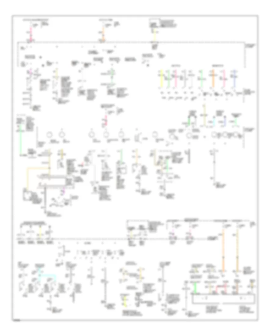
Instrument Cluster Wiring Diagram, Base for Oldsmobile Ninety-Eight Regency 1994
 https://portal-diagnostov.com/license.html
Automotive Electricians Portal FZCO
Automotive Electricians Portal FZCO
https://portal-diagnostov.com/license.html
https://portal-diagnostov.com/license.html
Automotive Electricians Portal FZCO
Automotive Electricians Portal FZCO
List of elements for Instrument Cluster Wiring Diagram, Base for Oldsmobile Ninety-Eight Regency 1994:
- (left side of engine compt)
- (middle of right kick panel)
- Acc
- Amp indicator
- Anti-lock diode (behind, i/p)
- Antilock brake system
- Antilock indicator
- B4 red b
- Bat
- Brake fluid level switch (closed w/ low fluid level)
- Brake indicator
- Brake warning input
- Bulb test
- C10
- C12
- C13
- C14
- C15
- C16
- Ccr switch (lower left side of i/p) (part of tcs switch)
- Check oil indicator
- Cluster
- Computer command ride controller (below left front seat)
- Coolant temp input
- D10
- D11
- D12
- D13
- D14
- D15
- D16
- Diagnostic energy reserve module (behind center of i/p)
- Electronic brake/traction control module (left side of engine compt)
- Engine coolant temp. gauge
- Engine coolant temperature sender (top left side of engine) (hot-55 ) (cold-1365 )
- Engine oil pressure input
- Engine running input
- Exterior lights system
- Fasten belts indicator
- Firm
- Firm input
- Firm ride indicator
- Fuel gauge
- Fuel gauge sender (top of fuel tank) (full-90 ) (empty-0 )
- Fuel level input
- Fuse 1d 15a
- Fuse 5a 10a
- Fuse 8 10a
- Fuse 9c 10a
- G100 (left front of engine compt)
- G102
- G119 (right front of engine)
- G200 (middle of left kick panel)
- G203
- G203 (middle of right kick panel)
- Gen in
- Gen out
- Generator (right side of engine)
- Gnd
- Headlights system
- Hi beam indicator
- Hot at all times
- Hot in run
- Hot in run, bulb test or start
- Hot indi- cator
- I/p fuse block
- Ign
- Ignition switch
- Illum- ination (5 bulbs)
- Indicator control
- Inflatable restraint indicator
- Instrument
- Instrument cluster
- Interior lights system
- Left turn indicator
- Lock
- Low coolant indicator
- Low coolant level sensor (front of engine compt, right rear of radiator)
- Low fuel indicator
- Low oil level sensor (lower left front of engine)
- Low wash fluid indicator
- Malfunction indicator
- Master cylinder reservoir (left rear of engine compt)
- Multi-function chime control module (behind center of i/p)
- Multi-function chime control module (behind right side of i/p)
- Multi-function chime module (behind center of i/p)
- Nca
- Normal
- Normal input
- Odometers
- Off
- Oil level module (behind right side of i/p)
- Oil pressure indicator
- Oil pressure switch (lower right rear of engine) (opens above 27kpa)
- Park brake switch (opens w/ park brake released)
- Pass-key ii decoder module (behind top right side of i/p)
- Pnk
- Power
- Powertrain control module (right side of i/p)
- Red
- Relay center
- Right turn indicator
- Run
- Security indicator
- Signal input
- Signal output
- Solid state
- Speedometer
- Start
- Tan
- Traction engaged indicator
- Traction off indicator
- Vehicle speed output
- W/ y67
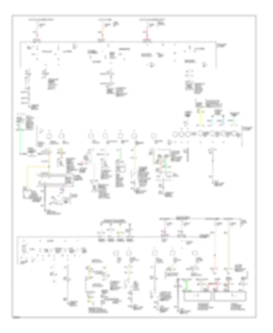
Instrument Cluster Wiring Diagram, Electronic for Oldsmobile Ninety-Eight Regency 1994
List of elements for Instrument Cluster Wiring Diagram, Electronic for Oldsmobile Ninety-Eight Regency 1994:
- (left front of engine compt)
- (park/neutral position switch)
- (top left side of engine)
- Abs ind. ctrl
- Acc
- Adaptive lamp monitor module (behind i/p, right of steering column)
- Air bag ind.
- Anti- lock diode
- Anti- lock ind.
- Antilock brakes system
- Brake fault input
- Brake fluid level switch
- Brake indicator
- Brake warning diode
- Brake warning input
- C10
- C11
- C12
- C16
- Ccr switch
- Chime
- Chime ctrl
- Computer command ride controller (below left front seat)
- Connector
- Control circuit
- Crank input
- D11
- D13
- D15
- D16
- Data link
- Date/ et
- Diagnostic energy reserve module (behind i/p, right of accelerator pedal)
- Dimming control
- Dk pnk
- Driver information center
- E13
- E14
- E6 tan
- E9 serial data request
- Econ
- Ects input
- Electronic brake & traction control module (attached to left front strut tower)
- Electronic ignition module (top right front of engine)
- Enable input a2
- Enable prndl-a
- Enable prndl-b
- Enable prndl-c
- Enable prndl-p
- Engine controls system
- Engine coolant
- Engine speed output
- Engine speed input
- English/ metric input
- Exterior lights system
- F10
- F12
- F13
- F14
- Fasten belts ind. ctrl
- Fasten belts input
- Firm
- Firm input c5
- Firm ride ind.
- Fuel
- Fuel gauge sender (top of fuel tank) (full-90 ) (empty-0 )
- Fuse 1a 10a
- Fuse 1d 15a
- Fuse 5a 10a
- Fuse 8 10a
- Fuse 9c 10a
- Fuse 9c 15a
- Fuse block: i/p
- G100
- G200 (below left side of i/p)
- G203 (below right side of i/p)
- Gauge
- Gnd
- Headlights
- Hi beam ind.
- Hot at all times
- Hot in run
- Hot in run bulb test or start
- Hot in run, bulb test or start
- Hot in start
- Ign input
- Ignition
- Ignition input
- Ignition switch
- Instrument cluster
- Interior lights system
- Led ctrls
- Left front door ajar input
- Left front door latch switch
- Left front door lock switch
- Left rear door lock switch
- Left turn ind.
- Lights on ind.
- Lock
- Low coolant level input
- Low coolant level output
- Low coolant level sensor (lower right rear of radiator)
- Low fuel input
- Low oil level input
- Low oil level output
- Low oil level sensor (lower left front of engine)
- Low washer fluid level input
- Malfunction ind.
- Master cylinder reservoir
- Memory input
- Mil ind. ctrl
- Multi- function chime module (behind i/p, right of steering column)
- Multi-function chime module (behind i/p, right of steering column)
- Nca
- Norm
- Norm input c4
- Off
- Oil
- Oil gauge pressure sender (3800-lower right rear of engine) (l67 sc-lower right side of engine) (high-80 ) (low-0 )
- Oil ind.
- Oil level module (behind right side of i/p)
- Oil press input
- Park brake switch (opens with park brake released)
- Pass- key ii decoder module (behind top right side of i/p)
- Pnk
- Pnk f16
- Power
- Powertrain control module (behind right side of i/p)
- Rear door ajar input
- Recall/ off
- Red
- Relay center
- Right front door ajar input
- Right front door lock switch
- Right rear door lock switch
- Right turn ind.
- Run
- Security ind.
- Security ind. ctrl
- Select
- Sense inputs
- Sensor return
- Serial data input
- Serial data output
- Set/ reset
- Signal input
- Signal output
- Sir ind. ctrl
- Solid state ctrl circuit
- Solid state fuel gauge
- Solid state odometer
- Solid state speedometer
- Start bulb test
- System
- Tan
- Tan d1
- Temperature sensor
- Test input
- Toggle
- Transient suppression
- Trip reset input
- Trip select input
- Uart data input/output
- Vehicle speed output
- Vehicle speed input
- Vf dim input
- Vf display input
- Washer fluid level switch (in windshield washer fluid reservoir)
Instrument Cluster Wiring Diagram, Gauges for Oldsmobile Ninety-Eight Regency 1994
List of elements for Instrument Cluster Wiring Diagram, Gauges for Oldsmobile Ninety-Eight Regency 1994:
- (left front of engine compt)
- (park/neutral position switch)
- (top left side of engine)
- Abs ind. ctrl
- Acc
- Air bag ind.
- Anti- lock diode
- Anti- lock ind.
- Antilock brakes system
- Brake fault input
- Brake fluid level switch
- Brake indicator
- Brake warning diode
- Brake warning input
- C16
- Ccr switch
- Check oil level ind.
- Chime
- Chime ctrl
- Computer command ride controller (below left front seat)
- Connector
- Crank input
- D11
- D13
- D15
- D16
- Data link
- Diagnostic energy reserve module (behind i/p, right of accelerator pedal)
- Driver door ajar ind.
- E13
- E14
- E6 tan
- Ects input
- Electronic brake & traction control module (attached to left front strut tower)
- Electronic ignition module (top right front of engine)
- Enable prndl-a
- Enable prndl-b
- Enable prndl-c
- Enable prndl-p
- Engine controls system
- Engine coolant
- Engine speed output
- English/ metric input
- Exterior lights system
- F12
- F13
- F14
- F16
- Fasten belts ind.
- Fasten belts ind. ctrl
- Firm
- Firm input c5
- Firm ride
- Fuel gauge
- Fuel gauge sender (top of fuel tank) (full-90 ) (empty-0 )
- Fuse 1a 10a
- Fuse 1d 15a
- Fuse 5a 10a
- Fuse 8 10a
- Fuse 9c 10a
- Fuse 9c 15a
- Fuse block: i/p
- G100
- G200 (below left side of i/p)
- G203 (below right side of i/p)
- Gnd
- Headlights
- Hi beam ind.
- Hot at all times
- Hot in run
- Hot in run bulb test or start
- Hot in run, bulb test or start
- Hot in start
- Ign input
- Ignition
- Ignition input
- Ignition switch
- Illum. lamps
- Ind.
- Instrument cluster
- Interior lights system
- Left front door latch switch
- Left turn ind.
- Lock
- Low coolant ind.
- Low coolant level output
- Low coolant level sensor (lower right rear of radiator)
- Low oil level output
- Low oil level sensor (lower left front of engine)
- Low washer fluid ind.
- Malfunction ind.
- Master cylinder reservoir
- Mil ind. ctrl
- Multi- function chime module (behind i/p, right of steering column)
- Multi-function chime module (behind i/p, right of steering column)
- Nca
- Norm
- Norm input c4
- Odometer
- Off
- Oil gauge pressure sender (3800-lower right rear of engine) (l67 sc-lower right side of engine) (high-86 ) (low-0 )
- Oil level module (behind right side of i/p)
- Oil pressure ind.
- Park brake switch (opens with park brake released)
- Park lamp ind.
- Pass- key ii decoder module (behind top right side of i/p)
- Pnk
- Power
- Powertrain control module (behind right side of i/p)
- Red
- Relay center
- Right turn ind.
- Run
- Security ind.
- Security ind. ctrl
- Sensor return
- Signal input
- Signal output
- Sir ind. ctrl
- Solid state ctrl circuit
- Speedometer
- Start bulb test
- System
- Tachometer
- Tan
- Tan d1
- Temperature sensor
- Test input
- Transient suppression
- Trip reset input
- Trip select input
- Uart data input/output
- Vehicle speed output
- Vf display input
- Voltmeter
- Washer fluid level switch (in windshield washer fluid reservoir)
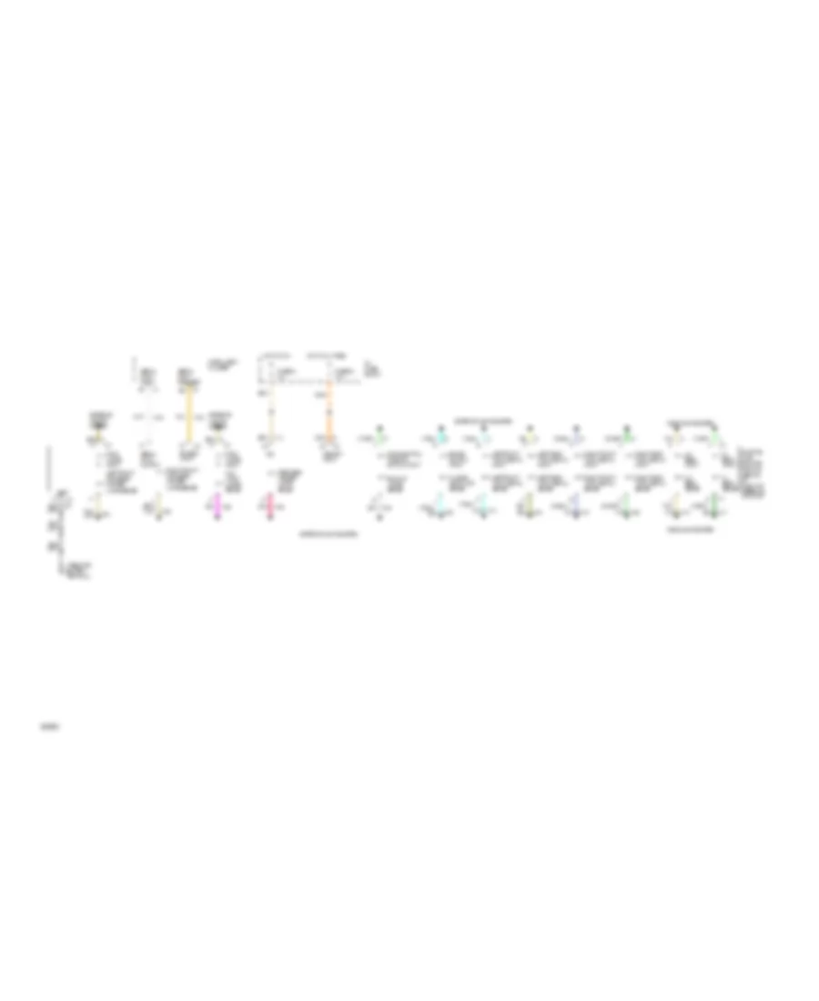
Lamp Monitor Wiring Diagram for Oldsmobile Ninety-Eight Regency 1994
List of elements for Lamp Monitor Wiring Diagram for Oldsmobile Ninety-Eight Regency 1994:
- A6 ign
- Adaptive lamp monitor module (behind i/p, right of steering column)
- Back up lamps sense
- Brake switch input
- Enable input
- Exterior lights system
- Fuse 5a 10a
- Fuse 9c 15a
- Headlights system
- Hi beam input
- Hi beam sense
- Hi level stop lamp sense
- Hot at all times
- Hot in run
- I/p fuse block
- Instrument cluster
- Left front park/side marker lamps sense
- Left front turn signal input
- Left front turn signal sense
- Left rear turn signal input
- Left rear turn signal sense
- Lo beam input
- Lo beam sense
- Memory input
- Park lamps input
- Park lamps input tail/ turn lamps sense
- Park/neutral position switch input
- Pnk
- Rear side marker/ lamps sense
- Right front park/side marker lamps sense
- Right front turn signal input
- Right front turn signal sense
- Right rear turn signal input
- Right rear turn signal sense
- Serial data input
- Serial data output
- Serial data request
- Tan

 Čeština
 Dansk
Dansk Ελληνικά
 English
 English
 Español
 Suomi
Suomi Français
 Français
 עברית
עברית Hrvatski
 Magyar
 Italiano
 日本語
日本語 한국어
한국어 Nederlands
 Polski
 Português
 Português
 Română
 Русский
 Slovenčina
 Slovenščina
 Svenska
 Türkçe
 中文 (中国)