ANTI-LOCK BRAKES
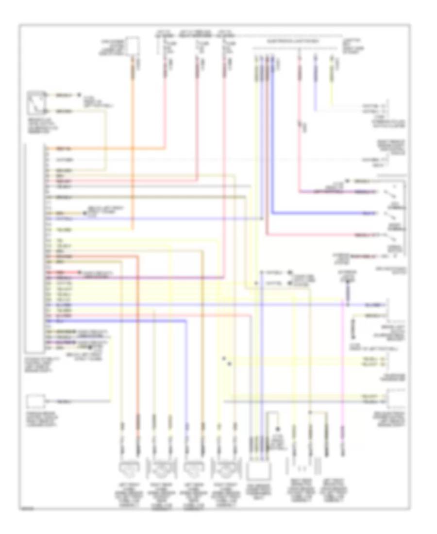
Anti-lock Brakes Wiring Diagram for BMW Z4 35i 2012
List of elements for Anti-lock Brakes Wiring Diagram for BMW Z4 35i 2012:
- (below left front strut tower) x170
- (right rear of engine compt) dme control module
- Brake fluid level switch (on brake fluid reservoir)
- Brake light switch (on brake pedal bracket)
- Car access system (under left side of dash)
- Computer data lines system
- Driving dynamic switch
- Dsc sensor (under front passenger's seat)
- Dtc button
- Dynamic stability control (dsc) (left side of engine compt)
- Edc electronic damper control (left rear of engine compt)
- Electronics junction box
- Exterior lights system
- Fuse 30a
- Fuse 40a
- Fuse 5a
- Hot at all times
- Hot w/ term 30g relay energized
- Interior lights system
- Junction box (right side of dash)
- Left front brake pad wear sensor (on left front wheel hub assembly)
- Left front wheel speed sensor (on left front wheel hub assembly)
- Left rear wheel speed sensor (on left rear wheel hub assembly)
- Nca
- Normal button
- Parking brake control module (right rear of luggage compt)
- Red
- Right front wheel speed sensor (on right front wheel hub assembly)
- Right rear brake pad wear sensor (on right rear wheel hub assembly)
- Right rear wheel speed sensor (on right rear wheel hub assembly)
- Sport button
- Steering column switch cluster
- Telephone transceiver
- X11001
- X11007
- X11008
- X1108 (front of left footwell)
- X13376
- X14271
- X14272
- X170 (below left front strut tower)
- X1880
- X60101
- X9331
 Čeština
 Dansk
Dansk Ελληνικά
 English
 English
 Español
 Suomi
Suomi Français
 Français
 עברית
עברית Hrvatski
 Magyar
 Italiano
 日本語
日本語 한국어
한국어 Nederlands
 Polski
 Português
 Português
 Română
 Русский
 Slovenčina
 Slovenščina
 Svenska
 Türkçe
 中文 (中国)
 Deutsch