CRUISE CONTROL
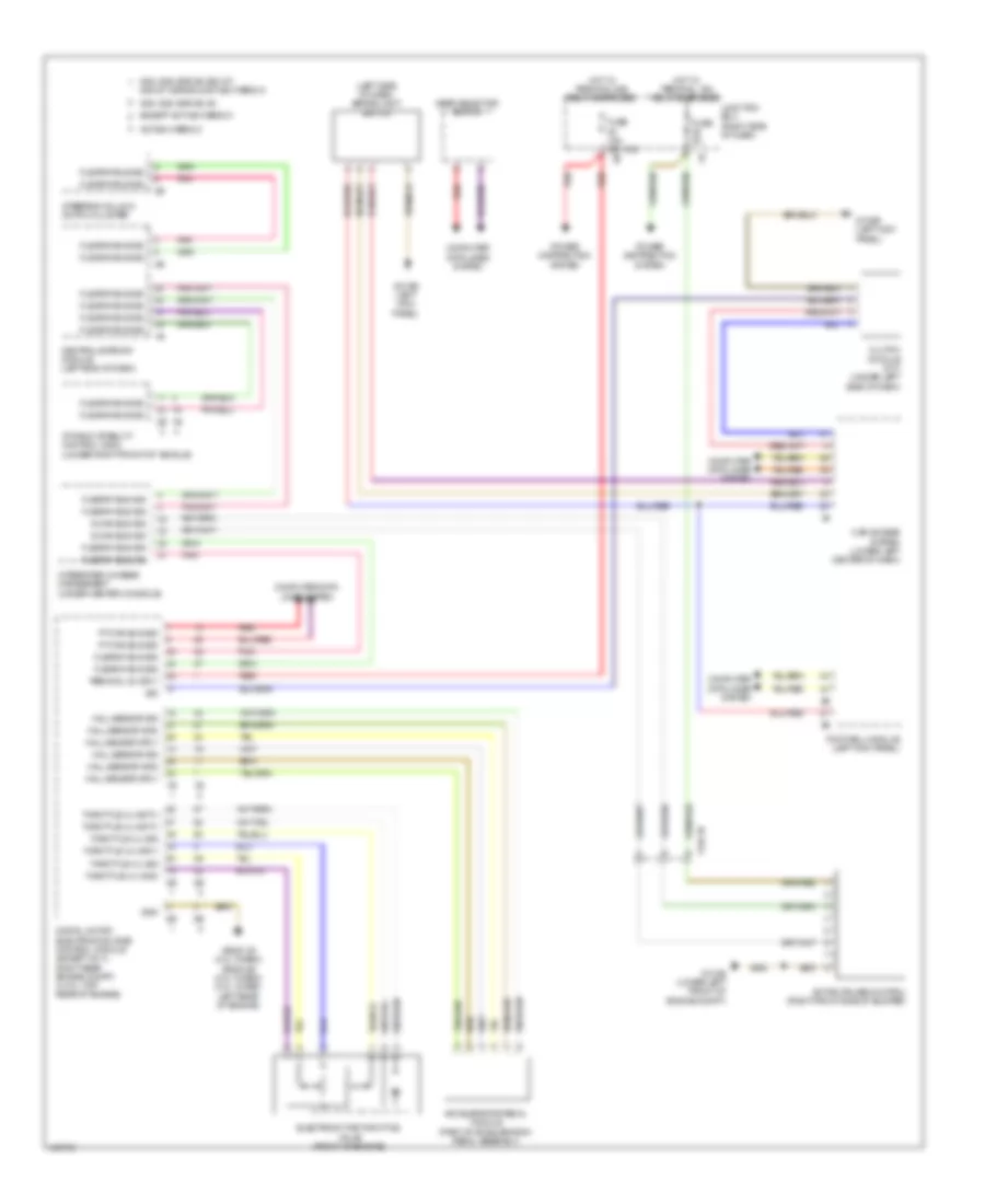
Cruise Control Wiring Diagram for BMW 535i GT 2014
List of elements for Cruise Control Wiring Diagram for BMW 535i GT 2014:
- (left side of dash) brake light switch
- 528i, 528i xdrive, m5
- 535i, 535i xdrive, 535i gt, 535i gt xdrive & active hybrid 5
- Accelerator pedal module (part of acceleration pedal assembly)
- Active cruise control (right front side of bumper)
- Active hybrid 5
- Car access system (lower left center of dash)
- Central gateway module (left end of dash)
- Clutch module (m/t) (under left side of dash)
- Computer data lines system
- Digital motor electronics (dme) control module (except 4cyl: right rear engine compt) (4 cyl: top rear of engine)
- Dynamic stability control (dsc) (under right front of vehicle)
- Electromotive throttle valve (front of engine)
- Except active hybrid 5
- Flexray bus sig
- Footwell module (left kick panel)
- Fuse 15a (0r 10a)
- Fuse 5a
- Gear selector switch
- Gnd
- Hall sensor gnd
- Hall sensor sig
- Hall sensor sply
- Hot w/ terminal 15n relay energized
- Hot w/ terminal 30b relay energized
- Integrated chassis management (under center console)
- Junction box (right side of dash)
- Pnk
- Power distribution system
- Pt-can bus sig
- Red
- S-can bus sig
- Sig
- Steering column switch cluster
- Terminal 30, sply
- Throttle vlv activ
- Throttle vlv gnd
- Throttle vlv sig
- Throttle vlv sply
- X148 1b
- Z10 2b (lower left front of engine compt)
- Z10 9b (left kick panel)
- Z6000 1b (3.0l turbo) z6000 4b (2.0l turbo) (3.0l turbo: left rear of engine)
 Čeština
 Dansk
Dansk Ελληνικά
 English
 English
 Español
 Suomi
Suomi Français
 Français
 עברית
עברית Hrvatski
 Magyar
 Italiano
 日本語
日本語 한국어
한국어 Nederlands
 Polski
 Português
 Português
 Română
 Русский
 Slovenčina
 Slovenščina
 Svenska
 Türkçe
 中文 (中国)
 Deutsch