INSTRUMENT CLUSTER
Electronic Night Vision Wiring Diagram for BMW 535i GT 2014


List of elements for Electronic Night Vision Wiring Diagram for BMW 535i GT 2014:
- 10b
- Basic w/ video switch
- Basic w/o video switch
- Computer data lines system
- Electronic night vision module
- Fuse 5a
- Head unit
- High
- Hot w/ terminal 15n relay energized
- Nca
- Night vision camera (left side of front bumper)
- Rear fuse holder (right side of rear compt)
- Red
- Video switch
- X4 1b
- Z10 12b (left rear of luggage compt)
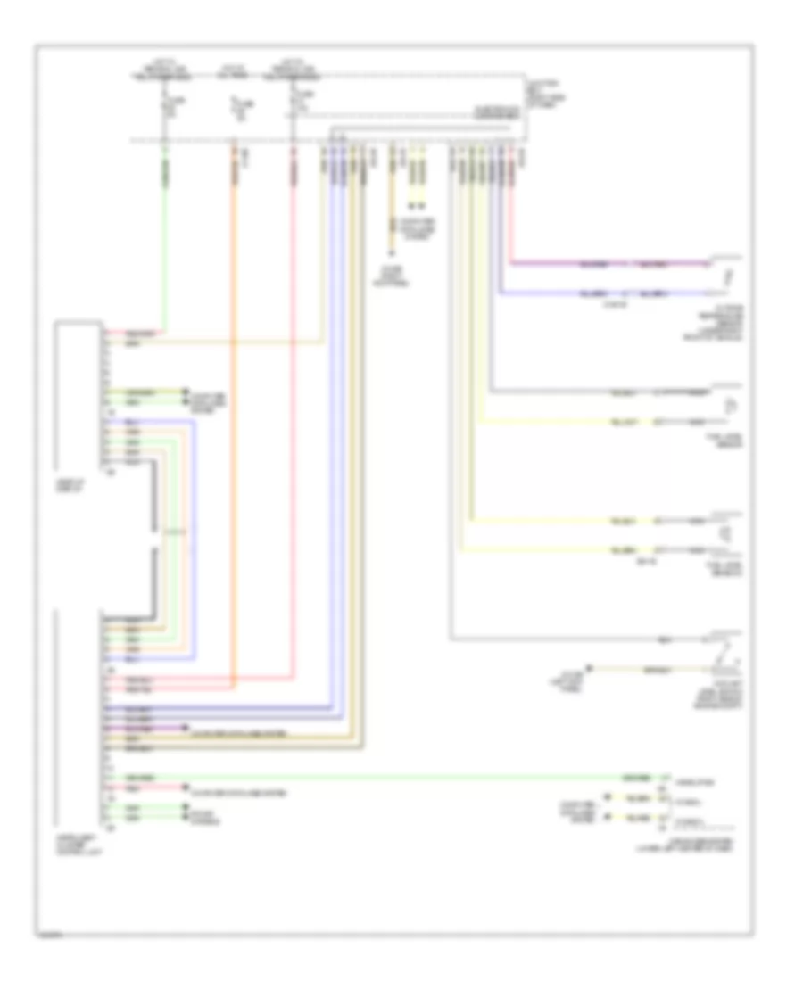
Instrument Cluster Wiring Diagram for BMW 535i GT 2014
List of elements for Instrument Cluster Wiring Diagram for BMW 535i GT 2014:
- A34 1b
- A34 2b
- A34 3b
- Car access system (lower left center of dash)
- Computer data lines system
- Coolant level switch (right side of engine compt)
- Electronics junction box
- Fuel level sensor
- Fuel level sensor 2
- Fuse 10a
- Fuse 5a
- Head-up display
- Hot at all times
- Hot w/ terminal 30b relay energized
- Instrument cluster control unit
- Junction box (right side of dash)
- K can2-h
- K can2-l
- Nca
- Outside temperature sensor (under right front of vehicle)
- Red
- Sound systems
- Wake up sig
- X149 1b
- X94 1b
- Z1 10b
- Z10 6b (right kick panel)
- Z10 9b (left kick panel)

 Čeština
 Dansk
Dansk Ελληνικά
 English
 English
 Español
 Suomi
Suomi Français
 Français
 עברית
עברית Hrvatski
 Magyar
 Italiano
 日本語
日本語 한국어
한국어 Nederlands
 Polski
 Português
 Português
 Română
 Русский
 Slovenčina
 Slovenščina
 Svenska
 Türkçe
 中文 (中国)