
 Čeština
 Dansk
Dansk Ελληνικά
 English
 English
 Español
 Suomi
Suomi Français
 Français
 עברית
עברית Hrvatski
 Magyar
 Italiano
 日本語
日本語 한국어
한국어 Nederlands
 Polski
 Português
 Português
 Română
 Русский
 Slovenčina
 Slovenščina
 Svenska
 Türkçe
 中文 (中国)

HORN
Horn Wiring Diagram for Mitsubishi Raider LS 2009
List of elements for Horn Wiring Diagram for Mitsubishi Raider LS 2009:
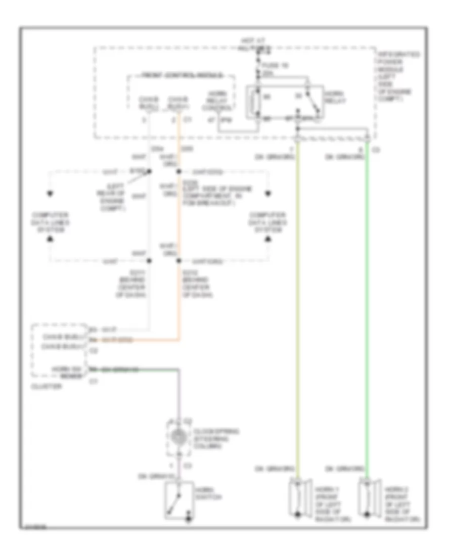

AIR CONDITIONINGANTI-LOCK BRAKESCRUISE CONTROLCOMPUTER DATA LINESBODY CONTROL MODULESDEFOGGERSANTI-THEFTENGINE PERFORMANCEEXTERIOR LIGHTSHEADLIGHTSGROUND DISTRIBUTIONHORNPOWER DISTRIBUTIONINTERIOR LIGHTSPOWER SEATSPOWER TOP/SUNROOFINSTRUMENT CLUSTERPOWER DOOR LOCKSPOWER MIRRORSRADIOSHIFT INTERLOCKPOWER WINDOWSSTARTING/CHARGINGWARNING SYSTEMSSUPPLEMENTAL RESTRAINTSTRANSMISSIONWIPER/WASHER