
 Čeština
 Dansk
Dansk Ελληνικά
 English
 English
 Español
 Suomi
Suomi Français
 Français
 עברית
עברית Hrvatski
 Magyar
 Italiano
 日本語
日本語 한국어
한국어 Nederlands
 Polski
 Português
 Português
 Română
 Русский
 Slovenčina
 Slovenščina
 Svenska
 Türkçe
 中文 (中国)

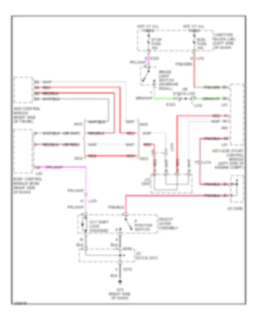
SHIFT INTERLOCK
Shift Interlock Wiring Diagram for Suzuki Kizashi GTS 2010
List of elements for Shift Interlock Wiring Diagram for Suzuki Kizashi GTS 2010:

AIR CONDITIONINGANTI-THEFTBODY CONTROL MODULESANTI-LOCK BRAKESELECTRONIC POWER STEERINGCOOLING FANENGINE PERFORMANCEDEFOGGERSCRUISE CONTROLCOMPUTER DATA LINESEXTERIOR LIGHTSGROUND DISTRIBUTIONINSTRUMENT CLUSTERPOWER DISTRIBUTIONHEADLIGHTSHORNPOWER DOOR LOCKSNAVIGATIONINTERIOR LIGHTSMEMORY SYSTEMSPOWER TOP/SUNROOFPOWER SEATSPOWER MIRRORSSUPPLEMENTAL RESTRAINTSPOWER WINDOWSTRANSMISSIONSTARTING/CHARGINGRADIOSHIFT INTERLOCKWARNING SYSTEMSWIPER/WASHER