NAVIGATION
COMAND Actuation Wiring Diagram for Mercedes-Benz CLS500 2006

List of elements for COMAND Actuation Wiring Diagram for Mercedes-Benz CLS500 2006:
MOST Data Bus Wiring Diagram for Mercedes-Benz CLS500 2006
List of elements for MOST Data Bus Wiring Diagram for Mercedes-Benz CLS500 2006:
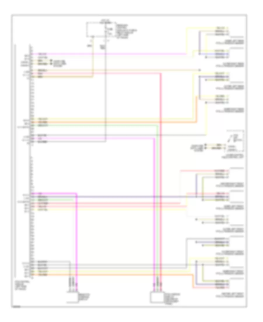
Navigation Wiring Diagram for Mercedes-Benz CLS500 2006
List of elements for Navigation Wiring Diagram for Mercedes-Benz CLS500 2006:
Parktronic Wiring Diagram, Early Production for Mercedes-Benz CLS500 2006
List of elements for Parktronic Wiring Diagram, Early Production for Mercedes-Benz CLS500 2006:
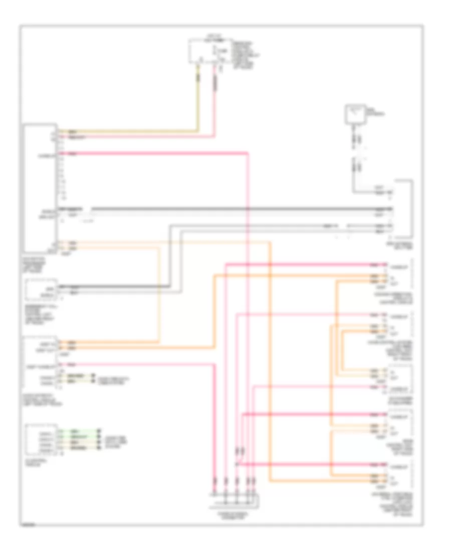
Parktronic Wiring Diagram, Late Production for Mercedes-Benz CLS500 2006
List of elements for Parktronic Wiring Diagram, Late Production for Mercedes-Benz CLS500 2006:
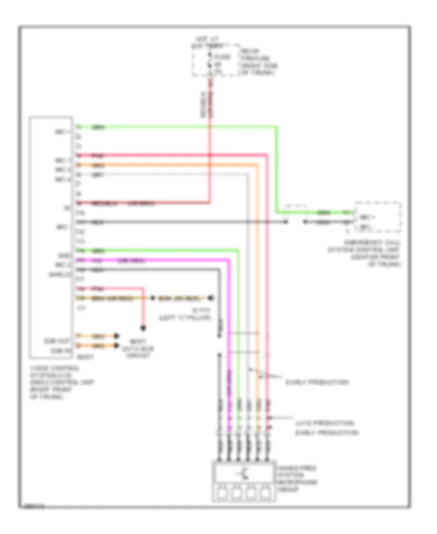
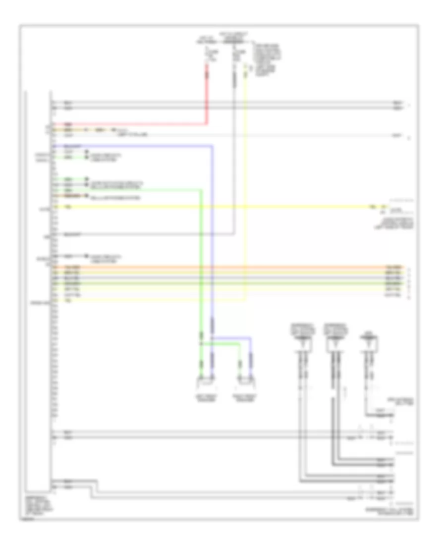
Tele Aid Wiring Diagram (1 of 2) for Mercedes-Benz CLS500 2006
List of elements for Tele Aid Wiring Diagram (1 of 2) for Mercedes-Benz CLS500 2006:
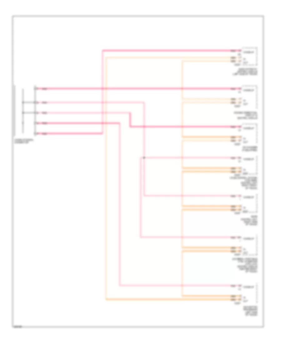
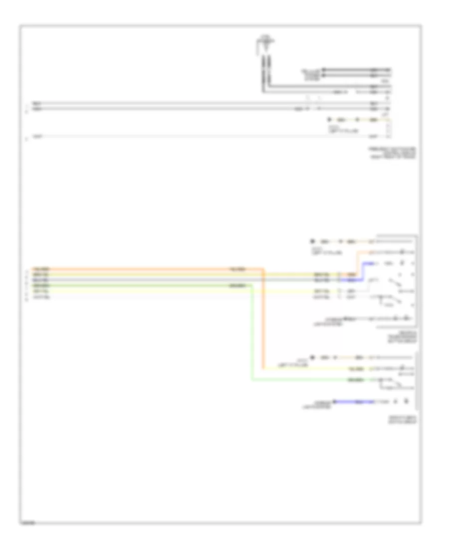
Tele Aid Wiring Diagram (2 of 2) for Mercedes-Benz CLS500 2006
List of elements for Tele Aid Wiring Diagram (2 of 2) for Mercedes-Benz CLS500 2006:
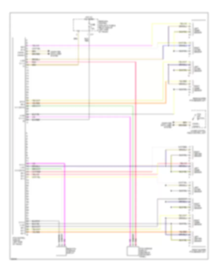
Voice Activation Wiring Diagram for Mercedes-Benz CLS500 2006
List of elements for Voice Activation Wiring Diagram for Mercedes-Benz CLS500 2006: