WARNING SYSTEMS
Warning Systems Wiring Diagram for Chevrolet Astro 2005
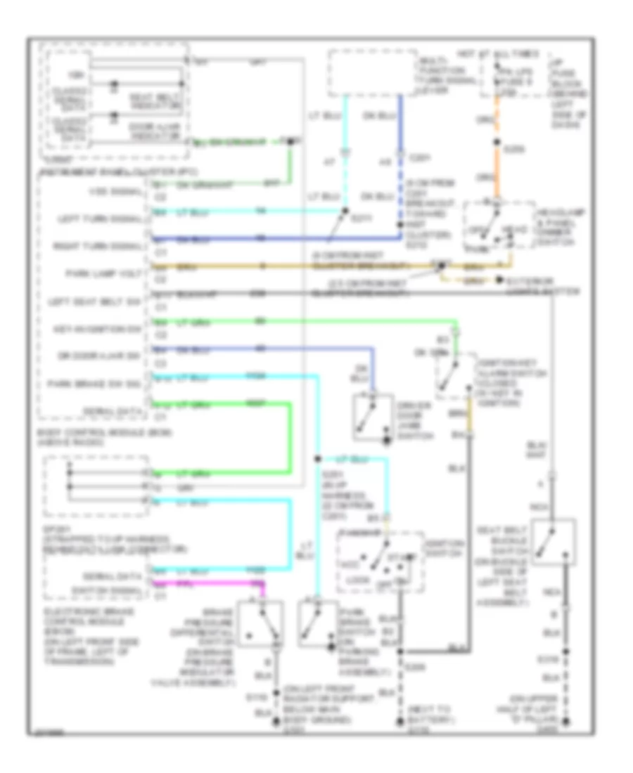
List of elements for Warning Systems Wiring Diagram for Chevrolet Astro 2005:
- (2.5 cm from inst cluster breakout)
- (6 cm from c201 breakout, toward inst cluster) s212
- (6 cm from inst cluster breakout)
- (next to battery) g110
- (on left front radiator support, below main body ground) g101
- (on upper half of left "d" pillar) g400
- A12
- Acc
- B10
- B11
- Body control module (bcm) (above radio)
- Brake pressure differential switch (on brake pressure modulator valve assembly)
- C201
- Class2 serial data
- Door ajar indicator
- Dr door ajar sw
- Driver door jamb switch
- Electronic brake control module (ebcm) (on left front side of frame, left of transmission)
- Exterior lights system
- Head
- Headlamp & panel dimmer switch
- Hot at all times
- I/p fuse block (behind left side of dash)
- Ign
- Ignition key alarm switch (closed w/ key in ignition)
- Ignition switch start
- Instrument panel cluster (ipc)
- Key-in ignition sw
- Left seat belt sw
- Left turn signal
- Lock
- Logic
- Multi- function turn signal lever
- Nca
- Off
- Park
- Park brake sw sig
- Park brake switch (on parking brake assembly)
- Park lamp volt
- Pk lps fuse 9 20a
- Right turn signal
- S110
- S130
- S206
- S211
- S217
- S251 (in i/p harness, 22 cm from c201)
- S256
- S319
- Seat belt buckle switch (on buckle side of left seat belt assembly)
- Seat belt indicator
- Serial data
- Sp261 (strapped to i/p harness, behind data link connector)
- Switch signal
- Vss signal
 Čeština
 Dansk
Dansk Ελληνικά
 English
 English
 Español
 Suomi
Suomi Français
 Français
 עברית
עברית Hrvatski
 Magyar
 Italiano
 日本語
日本語 한국어
한국어 Nederlands
 Polski
 Português
 Português
 Română
 Русский
 Slovenčina
 Slovenščina
 Svenska
 Türkçe
 中文 (中国)
 Deutsch