TRANSMISSION
3.0L
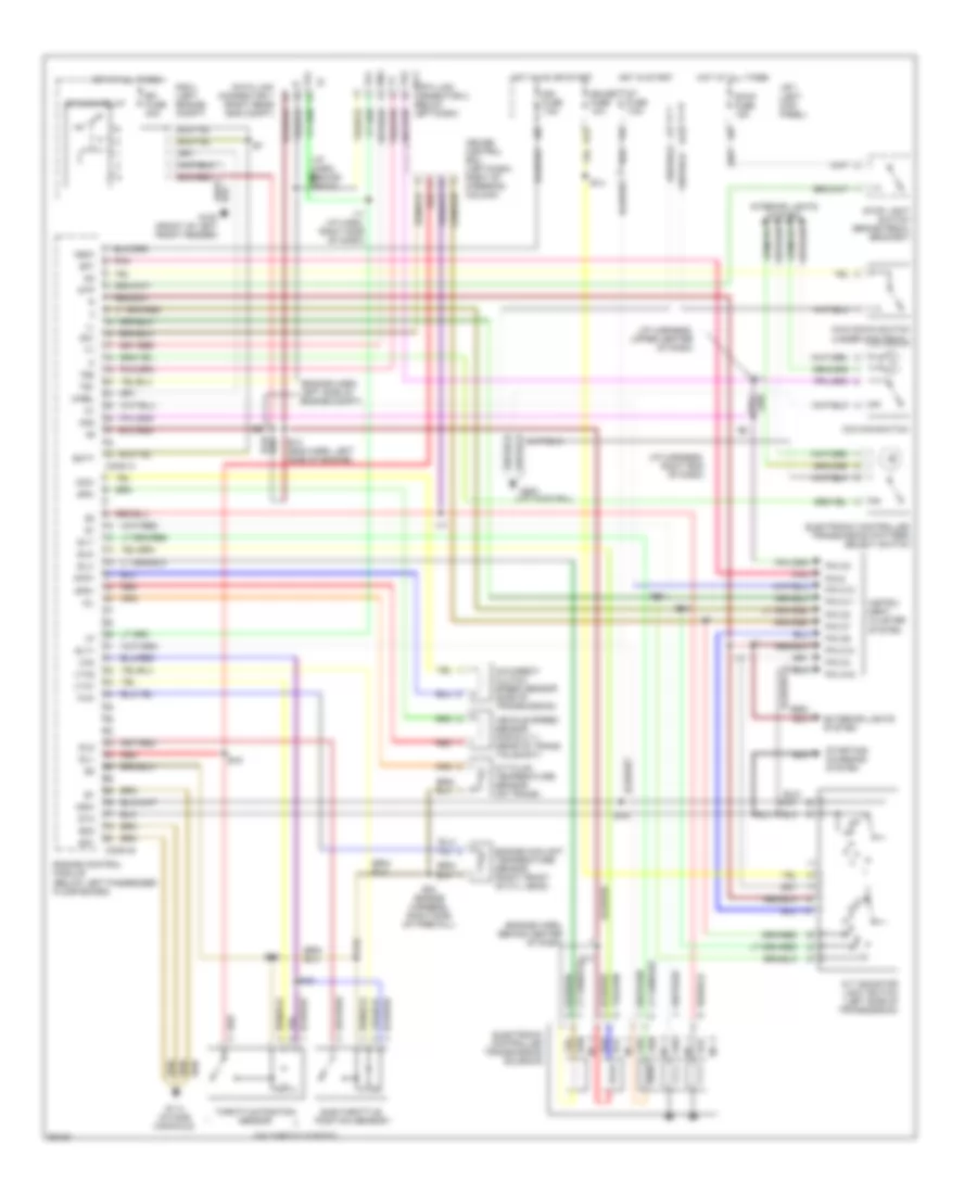
3.0L Non-Turbo, Transmission Wiring Diagram for Toyota Supra 1996
 https://portal-diagnostov.com/license.html
Automotive Electricians Portal FZCO
Automotive Electricians Portal FZCO
https://portal-diagnostov.com/license.html
https://portal-diagnostov.com/license.html
Automotive Electricians Portal FZCO
Automotive Electricians Portal FZCO
List of elements for 3.0L Non-Turbo, Transmission Wiring Diagram for Toyota Supra 1996:
- (engine harn, left rear of engine)
- (engine harn, right side of firewall)
- (engine harn, upper front of engine) e23
- (i/p harn, right side of dash)
- (i/p harn, right side of dash) i17
- (lft kick pnl)
- (under gas pedal)
- A/t fluid temperature sensor (on trans)
- A/t indicator light switch (left side of transmission)
- B6 (body harn, left quarter panel)
- Batt
- Conn a
- Conn b
- Cruise control ecu (left dash, right of steering column)
- E12
- E20
- E25 (engine harness, left side of engine compt)
- E26
- E28
- E28 (engine harn, right side of firewall)
- Efi fuse 30a
- Efi main relay
- Electronic controlled trans- mission pattern select switch
- Electronic controlled transmission solenoid
- Engine control module (below left passenger floor board)
- Engine coolant temperature sensor (left front of cyl head)
- Eo1
- Eo2
- Exterior lights system
- G100 (front of left front fender)
- G114 (intake manifold)
- G200
- Gauge fuse 10a
- H13
- Hot at all times
- Hot in on or start
- Hot in start
- I10
- I17
- I21 (i/p harn, right end of dash)
- I4 (i/p harn, left end of dash)
- Idl1
- Ign fuse 7.5a
- Igsw
- Instrument cluster system
- Interior lights system
- J/b 1 (left kick panel)
- Kick down switch
- M-rel
- Mass air flow sensor (behind air filter housing)
- No. 1
- No. 2
- No. 3
- Nsw
- O/d main switch
- Od1
- Od2
- Oil
- Pin 6
- Pin a16
- Pin c10
- Pin c11
- Pin c12
- Pin c2
- Pin c4
- Pin c6
- Pin c7
- Pin c8
- Pnk
- R/b 2 (left engine compt)
- Red
- Sp1
- Sp2+
- Sp2-
- St fuse 7.5a
- Sta
- Starting/ charging system
- Stop fuse 15a
- Stop light switch (brake pedal bracket)
- Stp
- Te1
- Te1 data link connector 1 (right rear eng compt)
- Tha
- Throttle position sensor (on throttle body)
- Thw
- Vcc
- Vehicle speed sensor (for e.c.t.) (rear of trans tailshaft)
- Vta1
3.0L Turbo, Transmission Wiring Diagram for Toyota Supra 1996
List of elements for 3.0L Turbo, Transmission Wiring Diagram for Toyota Supra 1996:
- (below left dash)
- (engine harn, behind center of dash)
- (engine harn, left side of engine compt)
- (i/p harn, behind radio) i16
- (i/p harness, right end of dash)
- (i/p harness, upper center of dash)
- (left kick panel)
- (on throttle body)
- (under gas pedal)
- A/t fluid temperature sensor (on trans)
- A/t indicator light switch (left side of transmission)
- Batt
- Conn a
- Conn b
- Cruise control ecu (left dash, right of steering column)
- Data link connector 2 ect
- E12
- E13 (eng harn, left side of engine)
- E14
- E16
- E16 (engine harness, right side of firewall)
- E17
- Efi fuse 30a
- Efi main relay
- Electronic controlled transmission pattern select switch
- Electronic controlled transmission solenoid
- Eng
- Engine control module (below left passenger floor board)
- Engine coolant temperature sensor (right front of cyl head)
- Eo1
- Eo2
- Exterior lights system
- G100 (front of left front fender)
- G114 (intake manifold)
- G200 (lft kick pnl)
- Gauge fuse 10a
- H13
- Hot at all times
- Hot in on or start
- Hot in start
- I10
- I11
- I17
- I17 (i/p harn, right side of dash)
- Idl1
- Idl2
- Ign fuse 7.5a
- Igsw
- Instru- ment cluster system
- Interior lights system
- J/b 1
- Kick down switch
- M-rel
- Nco+
- Nco-
- No. 1
- No. 2
- No. 3
- No. 4
- No. 5
- Nsw
- O/d direct clutch speed sensor (side of transmission)
- O/d main switch
- Od1
- Od2
- Oil
- Pin 6
- Pin a16
- Pin c10
- Pin c11
- Pin c12
- Pin c2
- Pin c4
- Pin c6
- Pin c7
- Pin c8
- Pnk
- R/b 2 (left engine compt)
- Red
- Sln-
- Slt+
- Slt-
- Slu-
- Sp1
- Sp2+
- Sp2-
- St fuse 7.5a
- Sta
- Starting/ charging system
- Stop fuse 15a
- Stop light switch (brake pedal bracket)
- Stp
- Sub-throttle position sensor
- Te1
- Te2
- Throttle position sensor
- Thw
- Vcc
- Vehicle speed sensor (for e.c.t.) (rear of trans tailshaft)
- Vta1
- Vta2

 Čeština
 Dansk
Dansk Ελληνικά
 English
 English
 Español
 Suomi
Suomi Français
 Français
 עברית
עברית Hrvatski
 Magyar
 Italiano
 日本語
日本語 한국어
한국어 Nederlands
 Polski
 Português
 Português
 Română
 Русский
 Slovenčina
 Slovenščina
 Svenska
 Türkçe
 中文 (中国)