Čeština
 Dansk
Dansk Ελληνικά
 English
 English
 Español
 Suomi
Suomi Français
 Français
 עברית
עברית Hrvatski
 Magyar
 Italiano
 日本語
日本語 한국어
한국어 Nederlands
 Polski
 Português
 Português
 Română
 Русский
 Slovenčina
 Slovenščina
 Svenska
 Türkçe
 中文 (中国)

Infiniti G35 x 2004 - 2004 ELECTRICAL Fuses & Circuit Breakers - G35 Coupe
Infiniti G35 x 2004 - IDENTIFICATION
WARNING: Vehicle is equipped with air bag supplemental restraint system. Before attempting ANY repairs involving steering column, instrument panel or related components, see AIR BAG SAFETY PRECAUTIONS and DISABLING & ACTIVATING AIR BAG SYSTEM in appropriate AIR BAG RESTRAINT SYSTEMS article in RESTRAINTS.
WARNING: Always disconnect battery ground cable before servicing high-current fuses. It is recommended that high-current fuses be replaced by a qualified technician.
CAUTION: When battery is disconnected, vehicle computer and memory systems may lose memory data. Driveability problems may exist until computer systems have completed a relearn cycle. See COMPUTER RELEARN PROCEDURES article in GENERAL INFORMATION before disconnecting battery.
Infiniti G35 x 2004 - ENGINE COMPARTMENT JUNCTION & RELAY BLOCKS Component Locations
NOTE: For engine compartment fuse, fusible link and relay box locations, see Fig. 1 .
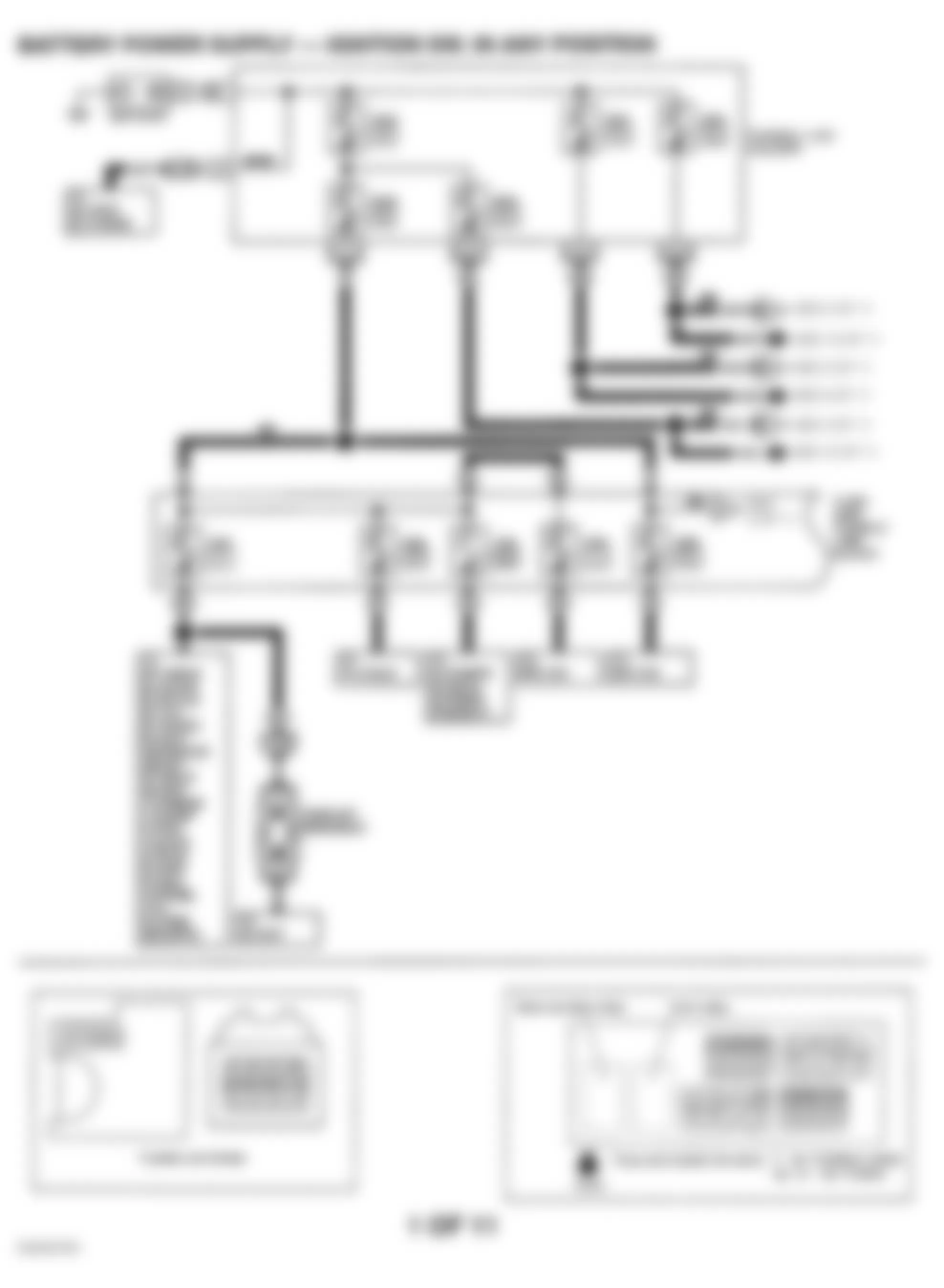
- Fuse and fusible link block is located at passenger's side of engine compartment. For component identification, see Fig. 4 and Fig. 5 . For circuit wiring diagram, see POWER DISTRIBUTION in SYSTEM WIRING DIAGRAMS article.
- Relay box, if manufactured in Canada, is located at passenger's side of engine compartment. For component descriptions, see Fig. 1 .
NOTE: VDC relays are not removable. - VDC Relay box is located at driver's side of engine compartment. See appropriate ANTI-LOCK/TRACTION CONTROL article in BRAKES.
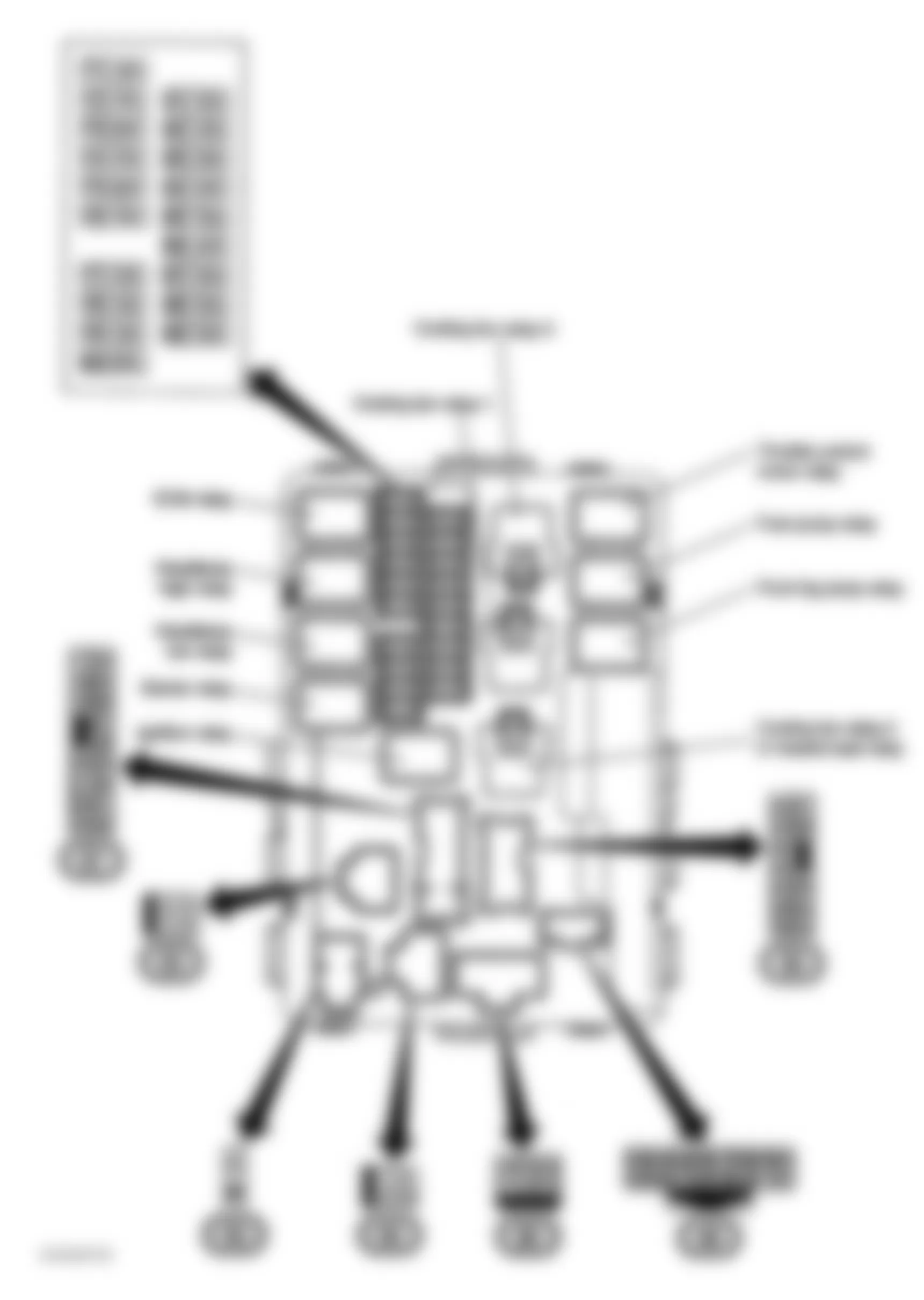
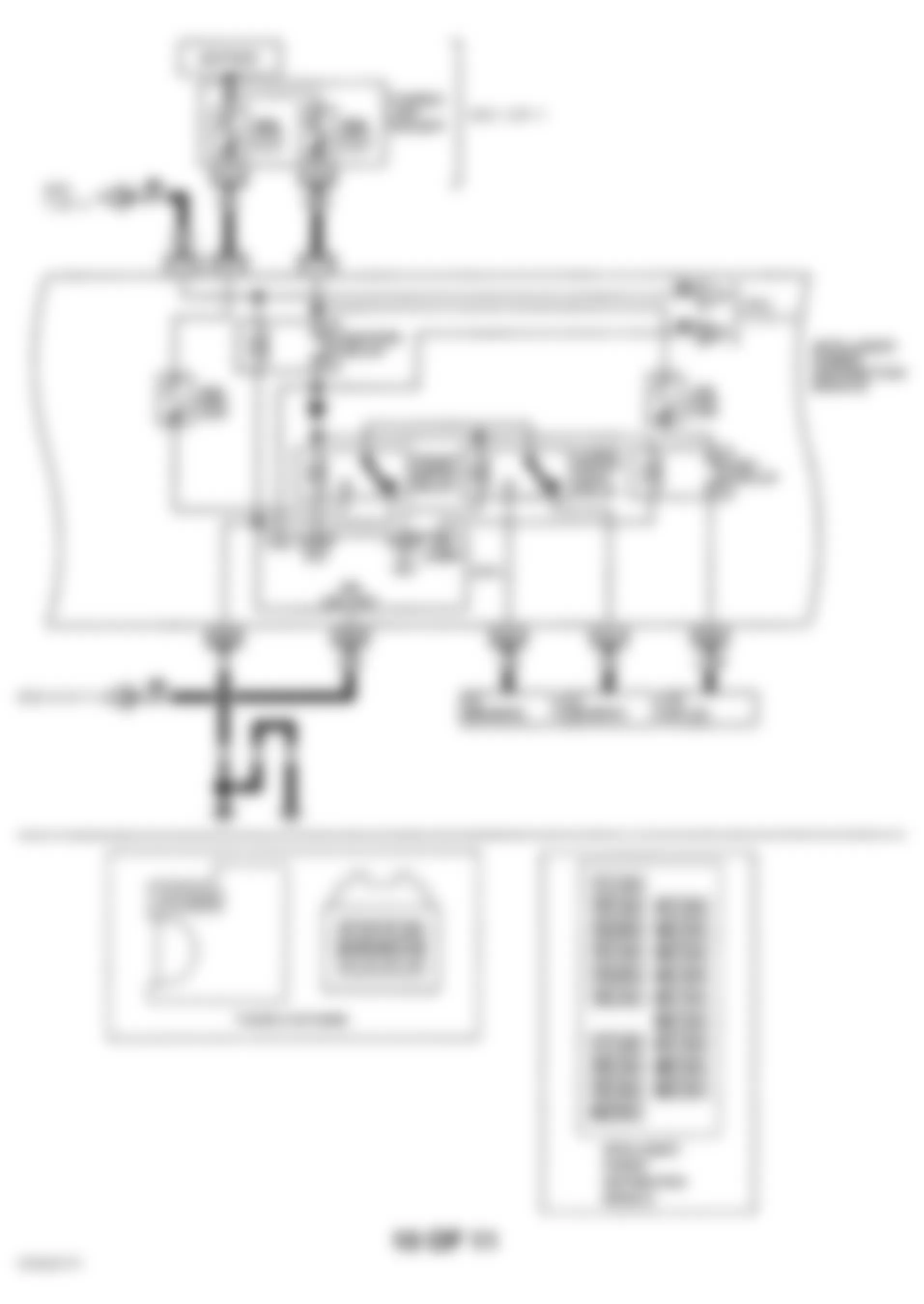
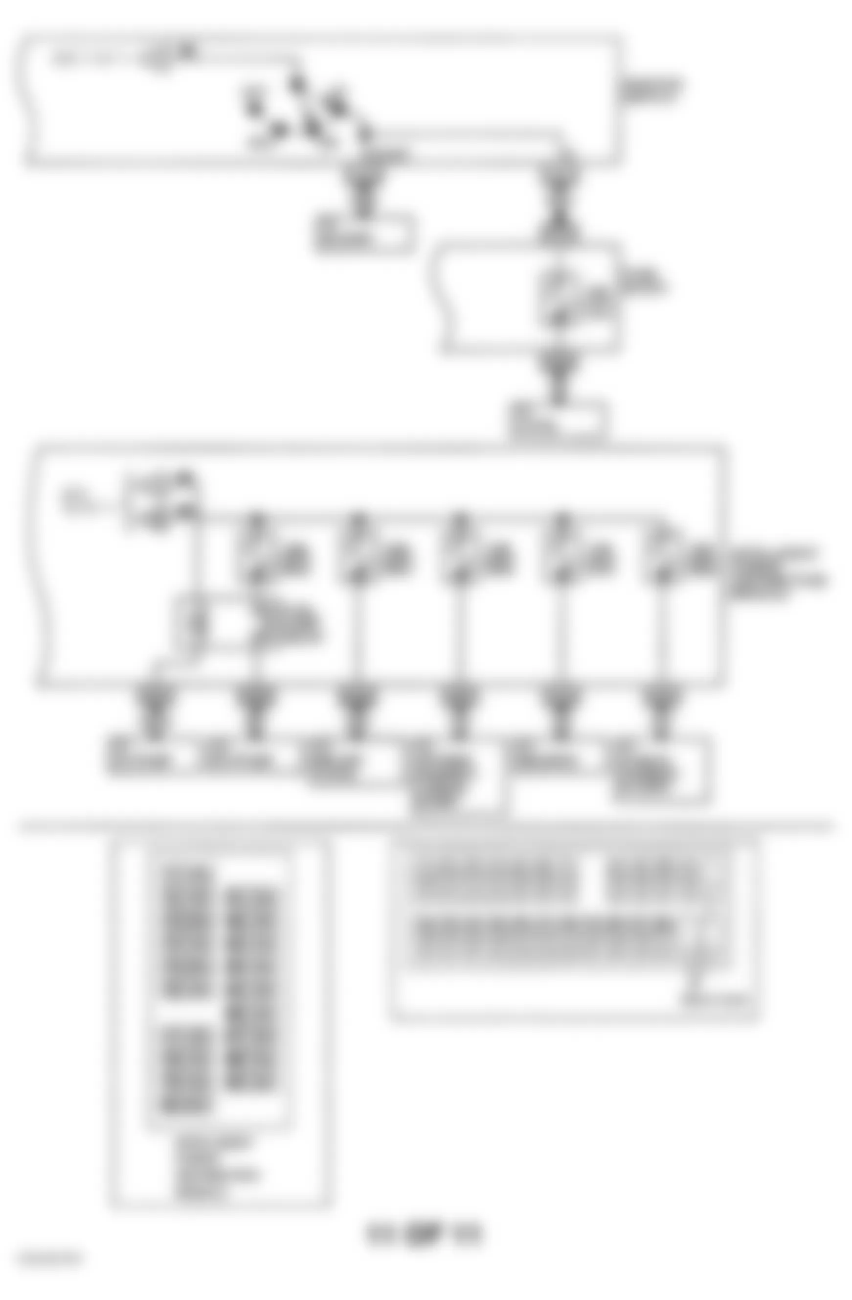
- Fusible link holder is located at passenger's side of engine compartment near battery connectors. For component locations, see Fig. 2 . For component identification, see Fig. 4 , Fig. 9 and Fig. 13 . For circuit wiring diagram, see POWER DISTRIBUTION in SYSTEM WIRING DIAGRAMS article.
NOTE: Relays in the Intelligent Power Distribution Module (IPDM) cannot be removed. - IPDM is located at passenger's side of engine compartment. For relay locations, see Fig. 3 . For component identification, see Fig. 6 -Fig. 8 and Fig. 12 -Fig. 14 . For circuit wiring diagram, see POWER DISTRIBUTION in SYSTEM WIRING DIAGRAMS article.


Fig. 2: Infiniti G35 x 2004 - Component Locations - Locating Fusible Link Holder Components
Infiniti G35 x 2004 - INSTRUMENT PANEL JUNCTION & RELAY BLOCKS Component Locations
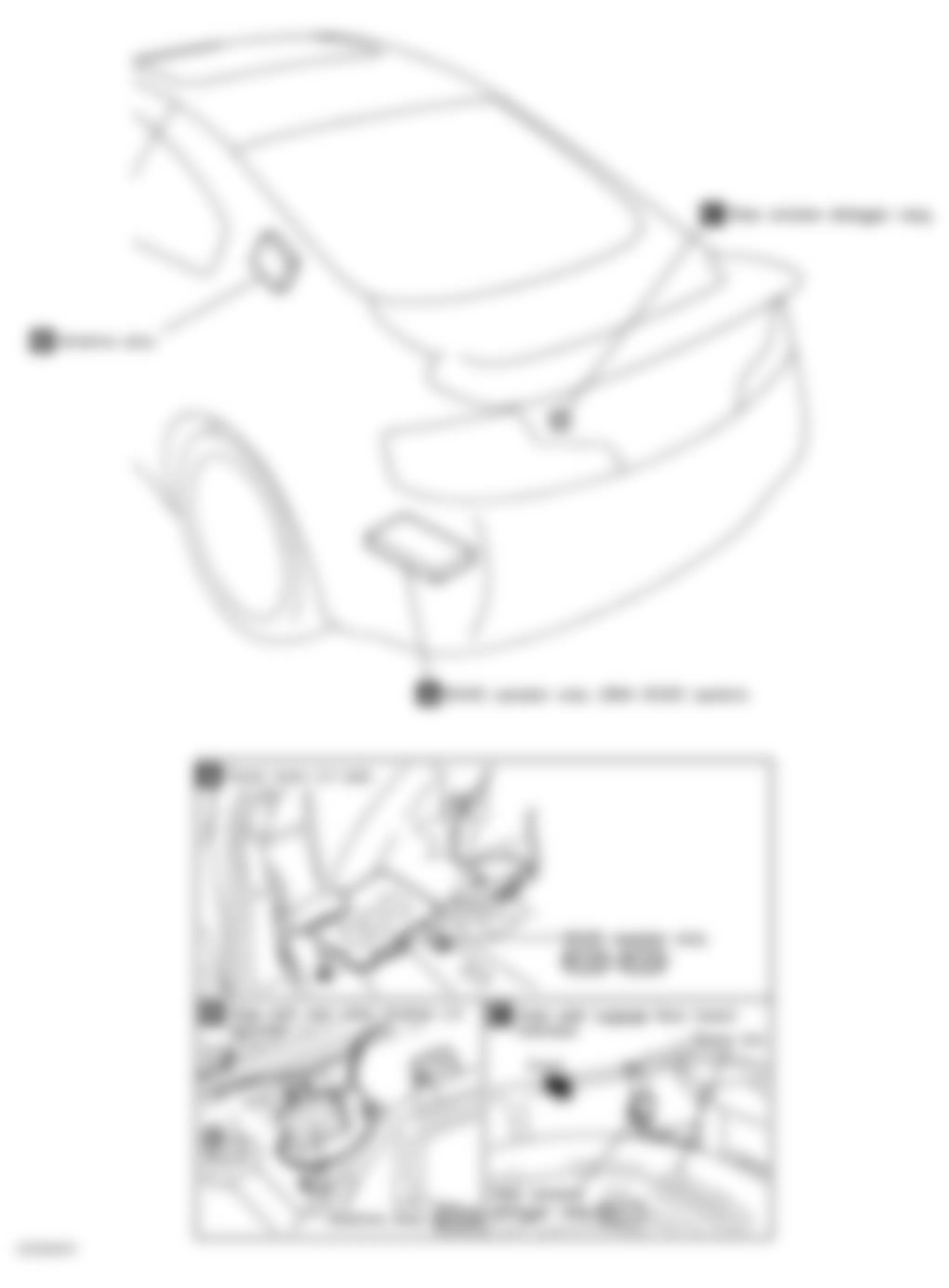
NOTE: For instrument panel and passenger area fuse block, relay, control module and unit locations, see Fig. 15 , Fig. 16 and Fig. 17 .
- Circuit breaker is located behind driver's side kick panel. For circuit breaker location, see Fig. 16 . For component identification, see Fig. 4 .
- Fuse block is located behind driver's side kick panel. For component identification, see Fig. 5 , Fig. 9 -Fig. 12 and Fig. 14 . For circuit wiring diagram, see POWER DISTRIBUTION in SYSTEM WIRING DIAGRAMS article.
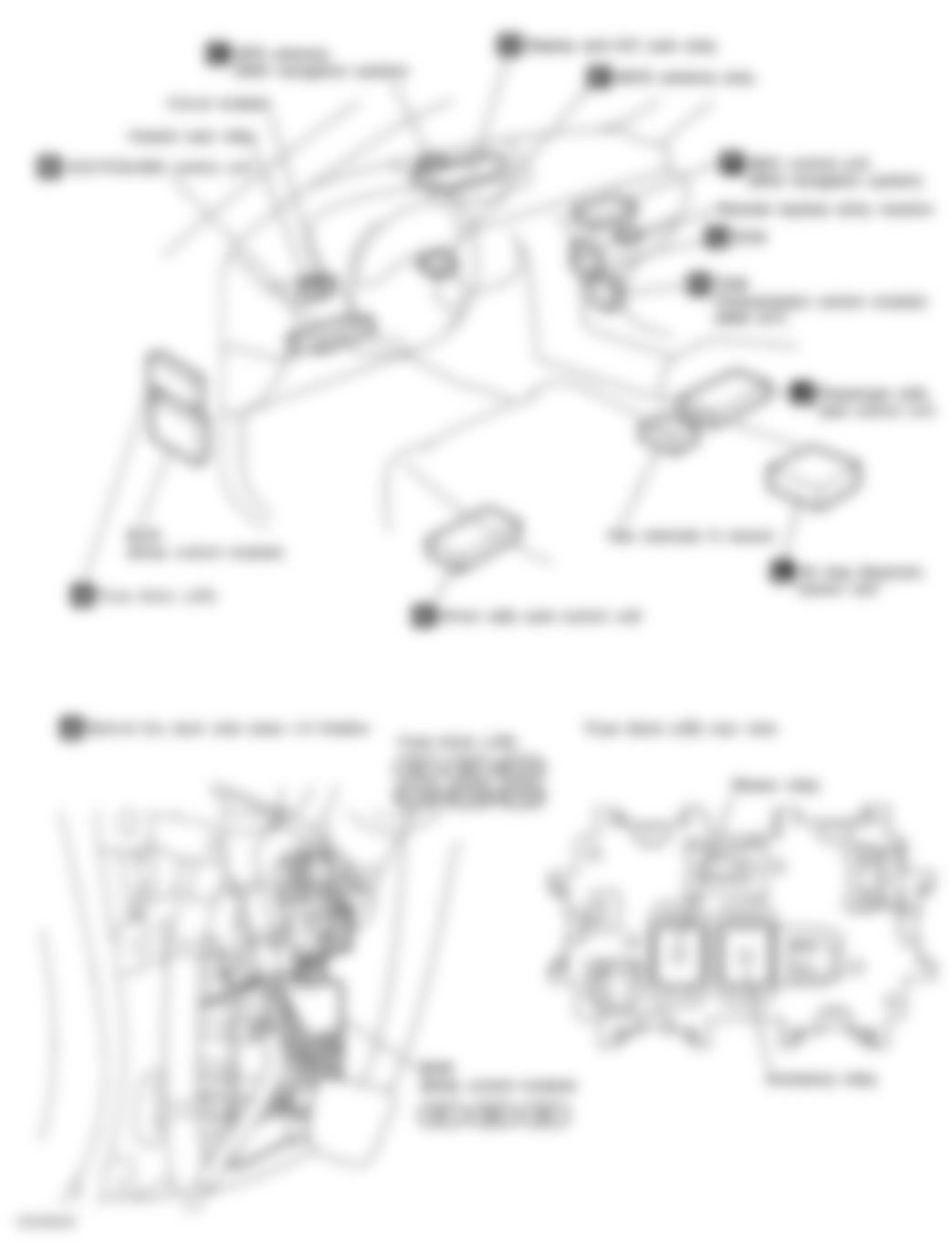
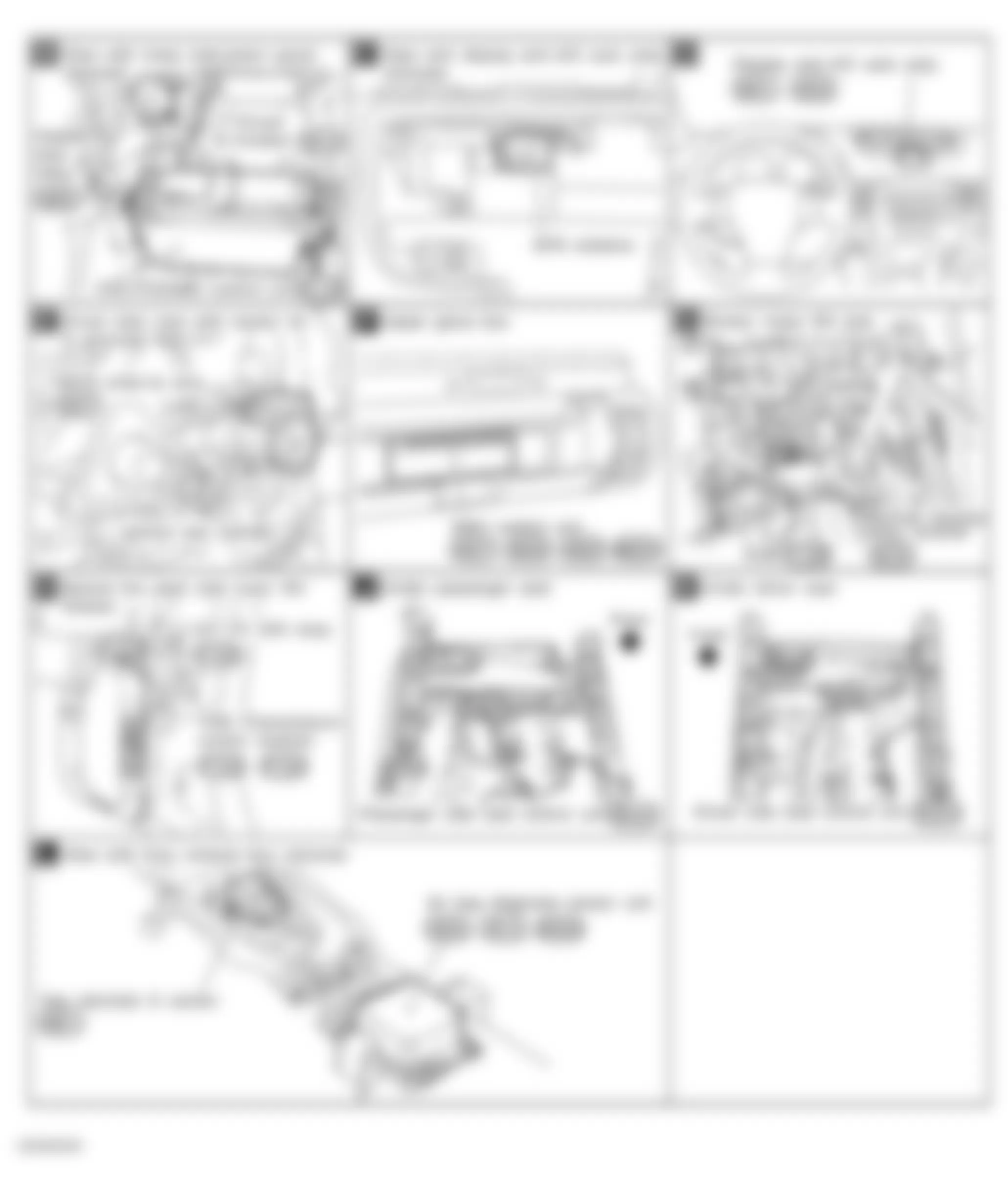
Fig. 17: Infiniti G35 x 2004 - Component Locations - Locating Luggage Compartment Relay