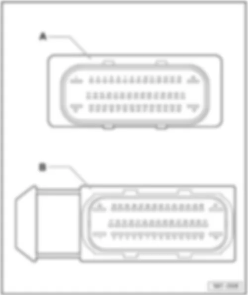
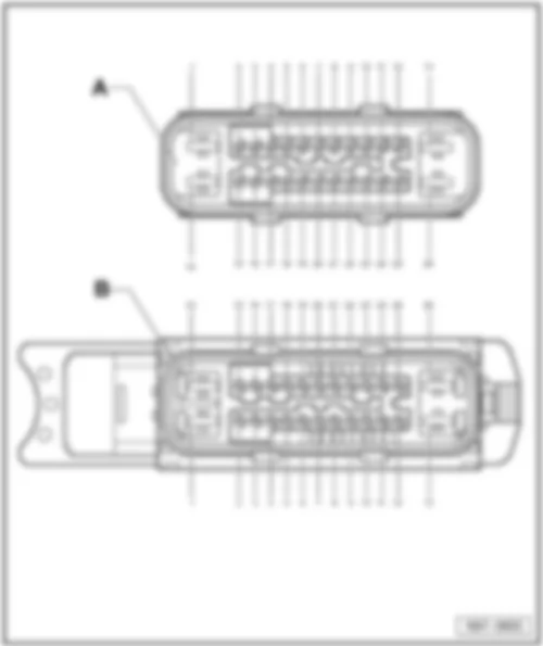
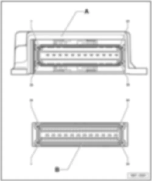
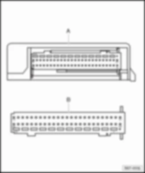
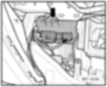
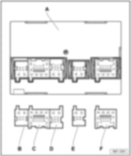
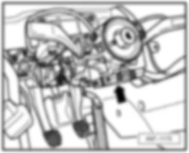
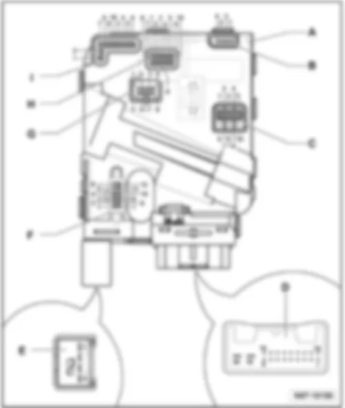
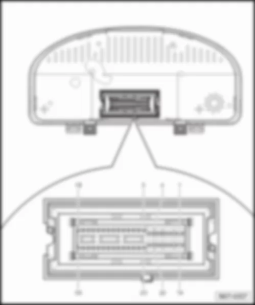
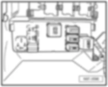
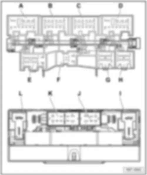
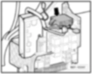
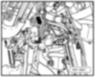
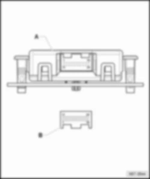
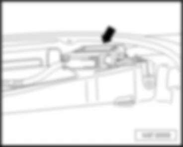
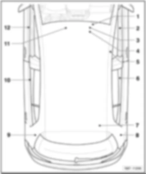
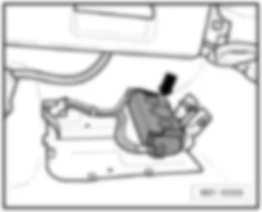
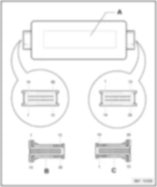
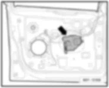
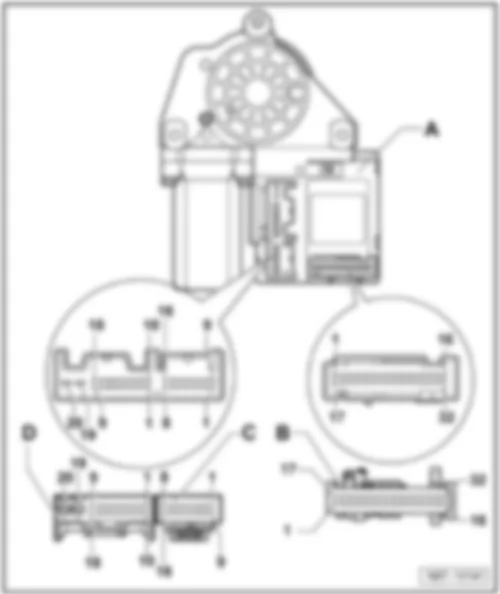
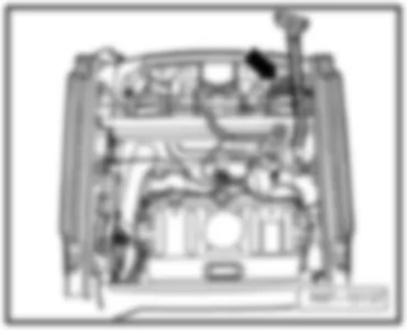
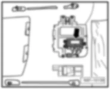
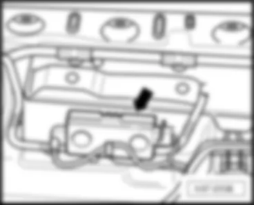
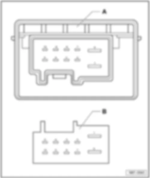
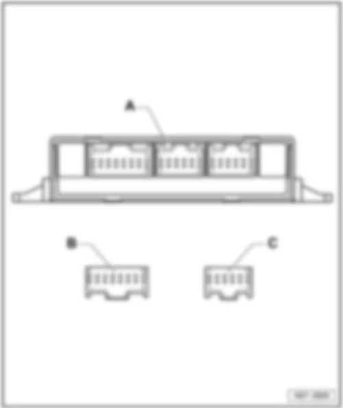
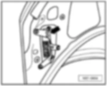
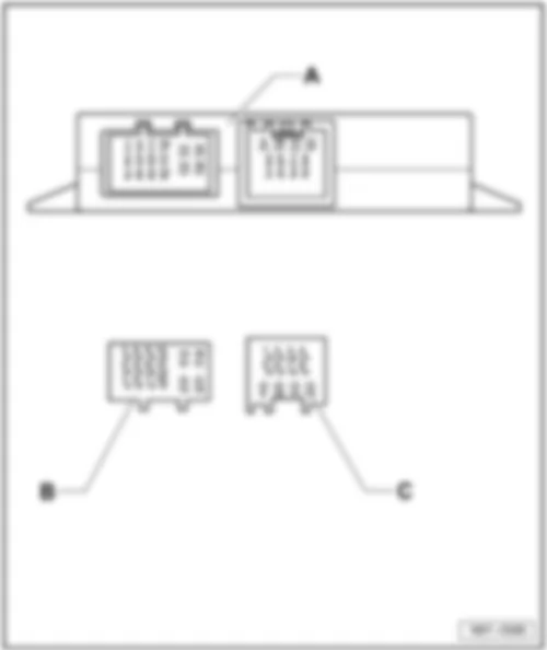
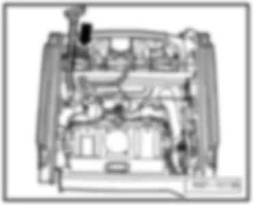
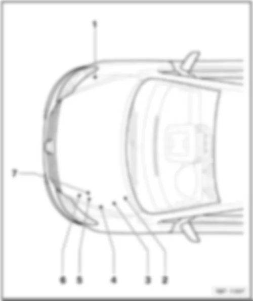
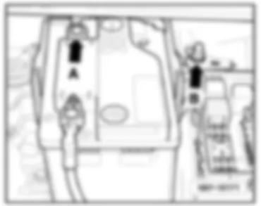
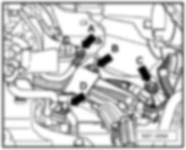
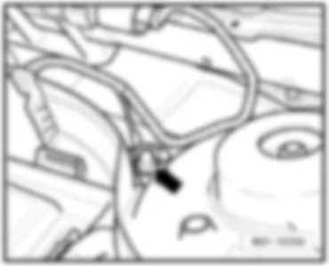
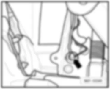
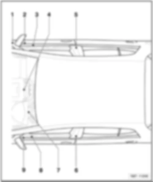
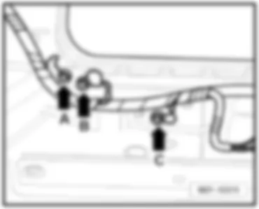
Wiring Diagram VW GOLF PLUS 2007 - Terminal 15 voltage supply relay 2 - fuses
Wiring Diagram VW GOLF PLUS 2007 - Driver door control unit - driver side window regulator motor - fuses
Wiring Diagram VW GOLF PLUS 2007 - Driver door control unit - window regulator switch in driver door - childproof lock button
| E40 | Front left window regulator switch |
| E53 | Rear left window regulator switch, in driver door |
| E55 | Rear right window regulator switch, in driver door |
| E81 | Front right window regulator switch in driver door |
| E318 | Childproof lock button |
| J386 | Driver door control unit |
| J519 | Onboard supply control unit |
| K236 | Warning light for activated childproof lock |
| L76 | Button illumination bulb |
| T10ad | 10-pin connector |
| T32a | 32-pin connector |
| 267 | Earth connection 2, in driver side door wiring harness |
| R75 | Connection 1 (58d), in door control unit wiring harness |
| x | From May 2007 |
| /// | To April 2007 |
Wiring Diagram VW GOLF PLUS 2007 - Driver door control unit - driver side interior locking button for central locking system - driver side central locking lock unit - central locking deadlock function warning lamp -SAFE-
| E308 | Driver side interior locking button for central locking system |
| F2 | Driver door contact switch |
| F220 | Driver side central locking lock unit |
| J386 | Driver door control unit |
| J519 | Onboard supply control unit |
| K133 | Central locking deadlock function warning lamp -SAFE- |
| K174 | Driver side interior locking warning lamp |
| L76 | Button illumination bulb |
| T2u | 2-pin connector, in driver door |
| T4an | 4-pin connector |
| T10z | 10-pin connector |
| T20a | 20-pin connector |
| T32a | 32-pin connector |
| V56 | Driver door central locking motor |
| V161 | Driver door central locking deadlock function motor |
| 267 | Earth connection 2, in driver side door wiring harness |
| R75 | Connection 1 (58d), in door control unit wiring harness |
Wiring Diagram VW GOLF PLUS 2007 - Driver door control unit - mirror adjustment switch and fold-in mirror switch - exterior mirror heater button - rear lid remote release switch
| E43 | Mirror adjustment switch |
| E48 | Mirror adjustment changeover switch |
| E231 | Exterior mirror heater button |
| E263 | Fold-in mirror switch |
| E319 | Fuel tank flap release button |
| J386 | Driver door control unit |
| J519 | Onboard supply control unit |
| L76 | Button illumination bulb |
| L78 | Mirror adjustment switch illumination bulb |
| T4ac | 4-pin connector |
| T6al | 6-pin connector |
| T32a | 32-pin connector |
| 303 | Earth connection 3, in driver side door wiring harness |
| R76 | Connection 2 (58d), in door control unit wiring harness |
| * | Only models with fold-in mirrors |
Wiring Diagram VW GOLF PLUS 2007 - Driver door control unit - heated exterior mirror relay - driver side mirror adjustment motor and driver side fold-in mirror motor - driver side exterior mirror turn signal bulb
| G353 | Potentiometer for horizontal adjustment of interior mirror |
| G354 | Potentiometer for vertical adjustment of interior mirror |
| J99 | Heated exterior mirror relay |
| J386 | Driver door control unit |
| J519 | Onboard supply control unit |
| L131 | Driver side exterior mirror turn signal bulb |
| T2ab | 2-pin connector |
| T2ac | 2-pin connector |
| T3g | 3-pin connector |
| T16a | 16-pin connector |
| T20a | 20-pin connector |
| T28 | 28-pin connector, coupling point, left A-pillar |
| V17 | Driver side mirror adjustment motor |
| V121 | Driver side fold-in mirror motor |
| V149 | Driver side mirror adjustment motor |
| Z4 | Driver side heated exterior mirror |
| 205 | Earth connection, in driver door wiring harness |
| * | Only models with fold-in mirrors |
| ## | Only models with automatic adjustment of mirror |
Wiring Diagram VW GOLF PLUS 2007 - Driver side entry light in exterior mirror - driver side automatic anti-dazzle exterior mirror - turn signal in front passenger side exterior mirror - heated exterior mirror on front passenger side
| J386 | Driver door control unit |
| J387 | Front passenger side door control unit |
| J519 | Onboard supply control unit |
| L132 | Front passenger side exterior mirror turn signal bulb |
| T2ad | 2-pin connector, on mirror |
| T2ah | 2-pin connector |
| T16a | 16-pin connector |
| T16g | 16-pin connector |
| T20a | 20-pin connector |
| T28 | 28-pin connector, coupling point, left A-pillar |
| W52 | Driver side entry light in exterior mirror |
| Y20 | Driver side automatic anti-dazzle exterior mirror |
| Z5 | Front passenger side heated exterior mirror |
| 205 | Earth connection, in driver door wiring harness |
| 206 | Earth connection, in front passenger door wiring harness |
| B397 | Connection 1 (convenience CAN bus, high), in main wiring harness |
| B406 | Connection 1 (convenience CAN bus, low), in main wiring harness |
| -●- | Only models with automatic anti-dazzle interior/exterior mirror |
Wiring Diagram VW GOLF PLUS 2007 - Front passenger door control unit - front passenger side mirror adjustment motor and fold-in mirror motor - entry light in front passenger side exterior mirror
| J387 | Front passenger side door control unit |
| J519 | Onboard supply control unit |
| T2ae | 2-pin connector |
| T3h | 3-pin connector |
| T16g | 16-pin connector |
| T20b | 20-pin connector |
| T28a | 28-pin connector, coupling point, right A-pillar |
| V25 | Front passenger side mirror adjustment motor |
| V122 | Front passenger side fold-in mirror motor |
| V150 | Front passenger side mirror adjustment motor |
| W53 | Front passenger side entry light in exterior mirror |
| 206 | Earth connection, in front passenger door wiring harness |
| * | Only models with fold-in mirrors |
| ## | Only models with automatic adjustment of mirror |
Wiring Diagram VW GOLF PLUS 2007 - Front passenger side door control unit - front passenger side central locking lock unit - window regulator switch in front passenger door - front passenger side window regulator motor
| E107 | Window regulator switch in front passenger door |
| F3 | Front passenger door contact switch |
| F221 | Front passenger side central locking lock unit |
| J387 | Front passenger side door control unit |
| J519 | Onboard supply control unit |
| L76 | Button illumination bulb |
| T4am | 4-pin connector |
| T10ab | 10-pin connector |
| T20b | 20-pin connector |
| T28a | 28-pin connector, coupling point, right A-pillar |
| T32b | 32-pin connector |
| V57 | Front passenger seat central locking motor |
| V148 | Front passenger side window regulator motor |
| V162 | Front passenger door central locking deadlock function motor |
| 47 | Earth point in front right footwell |
| 459 | Earth connection 15, in interior wiring harness |
Wiring Diagram VW GOLF PLUS 2007 - Rear left door control unit - rear left window regulator switch - rear left window regulator motor - rear left door contact switch - rear left central locking lock unit
Wiring Diagram VW GOLF PLUS 2007 - Rear right door control unit - rear right window regulator switch - rear right window regulator motor - rear right door contact switch - rear right central locking lock unit
| E54 | Rear right window regulator switch, in door |
| F11 | Rear right door contact switch |
| F223 | Rear right central locking lock unit |
| J389 | Rear right door control unit |
| J519 | Onboard supply control unit |
| L76 | Button illumination bulb |
| T4ay | 4-pin connector |
| T8t | 8-pin connector |
| T18d | 18-pin connector |
| T28c | 28-pin connector, right B-pillar coupling point |
| V27 | Rear right window regulator motor |
| V164 | Rear right door central deadlock function locking motor |
| V215 | Rear right door central locking motor, lock |
Wiring Diagram VW GOLF PLUS 2007 - Convenience system central control unit - rear lid release - rear lid lock unit - luggage compartment light
| E234 | Rear lid handle release button |
| F5 | Luggage compartment light switch |
| F256 | Rear lid lock unit |
| J393 | Convenience system central control unit, behind glove compartment |
| J519 | Onboard supply control unit |
| J533 | Data bus diagnosis interface |
| T4ab | 4-pin connector |
| T4ad | 4-pin connector |
| T5a | 5-pin connector, black, in rear left side panel |
| T5c | 5-pin connector, brown, in rear left side panel |
| T5e | 5-pin connector, pink, in rear left side panel |
| T8n | 8-pin connector |
| T18 | 18-pin connector |
| T20 | 20-pin connector |
| V139 | Rear lid release motor |
| W3 | Luggage compartment light |
| X | Number plate light |
| 98 | Earth connection, in rear lid wiring harness |
| 195 | Earth connection, in rear door switch wiring harness |
| 369 | Earth connection 4, in main wiring harness |
| 662 | Earth point, in rear left side panel |
| B397 | Connection 1 (convenience CAN bus, high), in main wiring harness |
| B406 | Connection 1 (convenience CAN bus, low), in main wiring harness |
Wiring Diagram VW GOLF PLUS 2007 - Convenience system central control unit - interior monitor deactivation switch - tank filler flap locking motor
Wiring Diagram VW GOLF PLUS 2007 - Convenience system central control unit - sliding sunroof adjustment control unit - sunroof button - sliding sunroof adjustment regulator - central locking and anti-theft alarm system aerial
| E139 | Sliding sunroof adjustment regulator |
| E325 | Sunroof button |
| J245 | Sliding sunroof adjustment control unit |
| J285 | Control unit in dash panel insert |
| J393 | Convenience system central control unit, behind glove compartment |
| J519 | Onboard supply control unit |
| L65 | Sliding sunroof switch illumination bulb |
| R47 | Central locking and anti-theft alarm system aerial |
| T2t | 2-pin connector |
| T6 | 6-pin connector |
| T6am | 6-pin connector |
| T6c | 6-pin connector |
| T6i | 6-pin connector |
| T8n | 8-pin connector |
| T18 | 18-pin connector |
| T36 | 36-pin connector |
| V1 | Sliding sunroof motor |
| 44 | Earth point, lower part of left A-pillar |
| B549 | Connection 2 (LIN bus), in main wiring harness |
| * | Only models with anti-theft alarm |
| --- | Only models with sliding sunroof adjustment control unit |
Wiring Diagram VW GOLF PLUS 2007 - Interior monitoring sensor - vehicle inclination sender - alarm horn
Wiring Diagram VW GOLF PLUS 2007 - Automatic anti-dazzle interior mirror - bonnet contact switch
| E386 | Anti-dazzle interior mirror button |
| F266 | Bonnet contact switch, in lock part |
| J519 | Onboard supply control unit |
| T2n | 2-pin connector, near right headlight |
| T6a | 6-pin connector |
| T6b | 6-pin connector |
| W1 | Front interior light |
| Y7 | Automatic anti-dazzle interior mirror |
| 378 | Earth connection 13, in main wiring harness |
| 389 | Earth connection 24, in main wiring harness |
| 656 | Earth point, on right headlight |
| A87 | Connection (RL), in dash panel wiring harness |
| -●- | Only models with automatic anti-dazzle interior/exterior mirror |
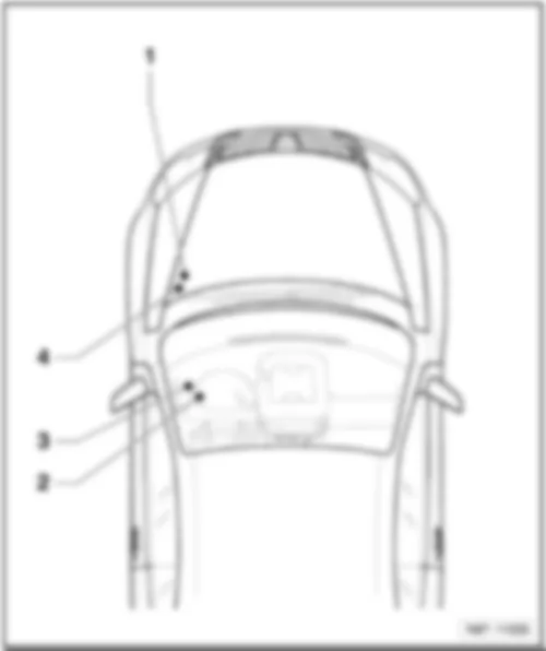
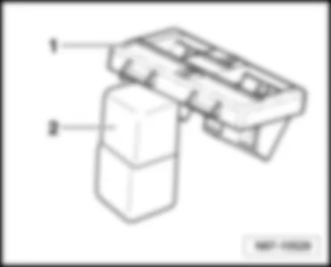
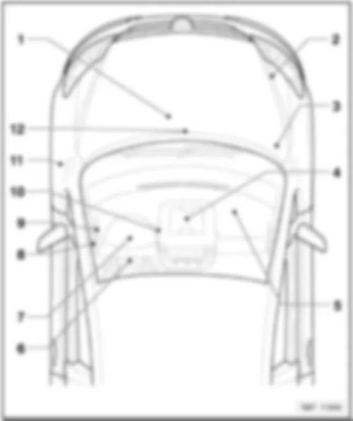
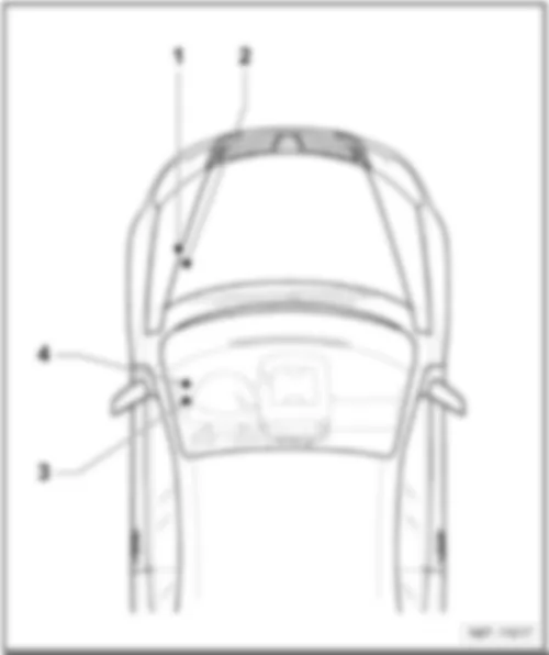
VW GOLF PLUS 2007 Overview of relay carrier
Overview of relay carrier | | | | 1 - | Relay carrier on E-box |
| q | On left in engine compartment |
| 2 - | Relay carrier on onboard supply control unit |
| 3 - | Relay carrier on left under dash panel |
| 4 - | Additional relay carrier under E-box |
| q | Under E-box, on left in engine compartment |
| q | Relay assignment, to April 2005 ⇒ page → 803/3 |
| Golf Plus | Fitting Locations | No. 803 / 2 |
|
| Relay locations on E-box low |
| 1 - | Terminal 30 voltage supply relay -J317- (458) |
| 1 - | Terminal 30 voltage supply relay -J317- (100) |
| 2 - | Secondary air pump relay -J299- (100) |
| q | Engine code BSX, from May 2005 |
| 2 - | Wiring bridge for automatic glow period control unit -J179- Glow plugs 1...4 -Q10...Q13- |
| q | Only vehicles with diesel engine |
| Golf Plus | Fitting Locations | No. 803 / 3 |
|
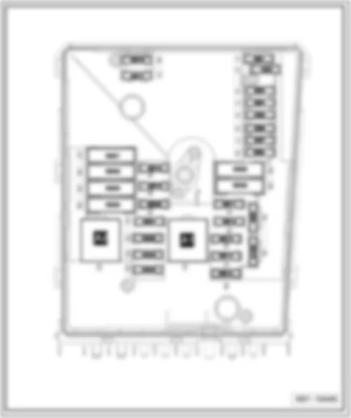
VW GOLF PLUS 2007 Relay locations on E-box high
Relay locations on E-box high |
| 1 - | Terminal 15 voltage supply relay -J329- (433) |
| 2 - | Relay for voltage supply of term. 50 -J682- (433) |
| 3 - | Engine components current supply relay -J757- (167) |
| 4 - | Terminal 30 voltage supply relay -J317- (458) |
| Golf Plus | Fitting Locations | No. 803 / 4 |
|
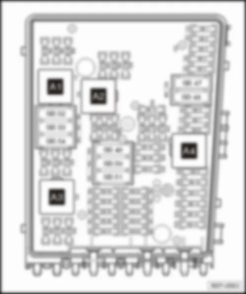
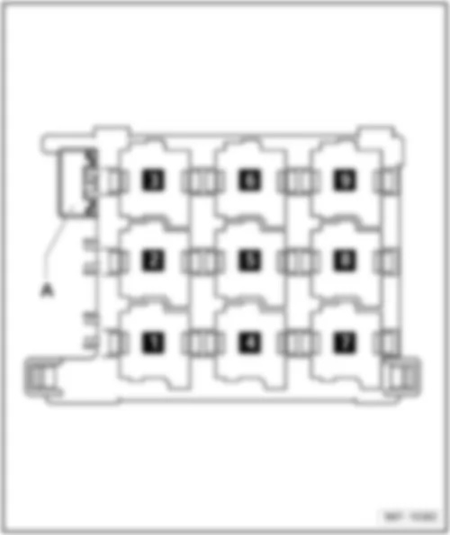
VW GOLF PLUS 2007 Relay assignment, relay carrier on onboard supply control unit, on left under dash panel
Relay assignment, relay carrier on onboard supply control unit, on left under dash panel |
| 1 - | Terminal 15 voltage supply relay 2 -J681- (460) |
| 2 - | Heated exterior mirror relay -J99- (449) |
| 3 - | Heated rear window relay -J9- (53) |
| 4 - | Dual tone horn relay -J4- (449) |
| 4 - | Horn relay -J413- (449) |
| 5 - | X-contact relief relay -J59- (460) |
| 6 - | Relay 1 for double washer pump -J729- (404) |
| Golf Plus | Fitting Locations | No. 803 / 5 |
|
| 6 - | Relay 2 for double washer pump -J730- (404) |
| 7 - | Relay 2 for double washer pump -J730- (404) |
| 7 - | Relay 1 for double washer pump -J729- (404) |
| 9 - | Terminal 30 voltage supply relay 2 -J689- (449) |
| Golf Plus | Fitting Locations | No. 803 / 6 |
|
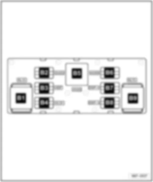
VW GOLF PLUS 2007 Relay assignment on left under dash panel, to April 2006
Relay assignment on left under dash panel, to April 2006 |
| 2 - | Terminal 50 voltage supply relay -J682- (433) |
| 3 - | Headlight washer system relay -J39- (53) |
| 5 - | Fresh air blower relay -J13- (404) |
| 6 - | Fuel pump relay -J17- (449) |
| 6 - | Relay for auxiliary heating mode -J485- (449) |
| Golf Plus | Fitting Locations | No. 803 / 7 |
|
| A - | Driver seat adjustment thermal fuse 1 - 30A |
Note:
| -J17- and -J485- are located in one relay slot depending on the equipment. |
| Golf Plus | Fitting Locations | No. 803 / 8 |
|
VW GOLF PLUS 2007 Relay assignment on left under dash panel, from May 2006
Relay assignment on left under dash panel, from May 2006 |
| 1 - | Fuel pump relay -J17- (449) |
| 1 - | Fuel supply relay -J643- (449) |
| 2 - | Terminal 50 voltage supply relay -J682- (53) |
| 3 - | Headlight washer system relay -J39- (53) |
| 4 - | Fresh air blower relay -J13- (404) |
| 5 - | Relay for low heater output -J359- (373) |
| 5 - | Fuel pump isolator relay -J333- (404) |
| 6 - | Relay for auxiliary heating mode -J485- (449) |
| Golf Plus | Fitting Locations | No. 803 / 9 |
|
| 6 - | High heat output relay |
| A - | Driver seat adjustment thermal fuse 1 - 30A |
Note:
| -J333-, -J13-, -J485- , -J360- and -J359- are installed depending on the equipment. Micro relays -J17- and -J643- are located in one relay slot |
| Golf Plus | Fitting Locations | No. 803 / 10 |
|
VW GOLF PLUS 2007 Relay assignment on left under dash panel, from May 2007
Relay assignment on left under dash panel, from May 2007 |
| 1 - | Fuel pump relay -J17- (449) |
| 1 - | Fuel system pressurisation relay -J643- (449) |
| 2 - | Relay for voltage supply of term. 50 -J682- (53) |
| 3 - | Headlight washer system relay -J39- (53) |
| 4 - | Fresh air blower relay -J13- (404) |
| 5 - | Relay for auxiliary heating mode -J485- (449) |
| 5 - | Relay for low heater output -J359- (373) |
| 6 - | Fuel pump isolator relay -J333- (404) |
| Golf Plus | Fitting Locations | No. 803 / 11 |
|
| 7 - | Fuel pump isolator relay -J333- (404) |
| 8 - | Relay for additional coolant pump -J496- (449) |
| A - | Driver seat adjustment thermal fuse 1 - 30A |
Note:
| -J333-, -J13-, -J485- , -J360- and -J359- are installed depending on the equipment. Micro relays -J17- and -J643- are located in one relay slot |
| Golf Plus | Fitting Locations | No. 803 / 12 |
|
| Relay assignment on additional relay carrier under E-box, on left in engine compartment, to April 2005 |
| 2 - | Automatic glow period control unit -J179- (461) |
Note:
| -The additional relay carrier is located under the E-box and is only visible when removed. |
| Golf Plus | Fitting Locations | No. 803 / 13 |
|
VW GOLF PLUS 2007 Relay assignment on additional relay carrier under E-box, on left in engine compartment, from May 2005 | Relay assignment on additional relay carrier under E-box, on left in engine compartment, from May 2005 | | 1 - | Additional relay carrier under E-box, on left in engine compartment | | 2 - | Automatic glow period control unit -J179- (461), from August 2006 code (457) | | |
|