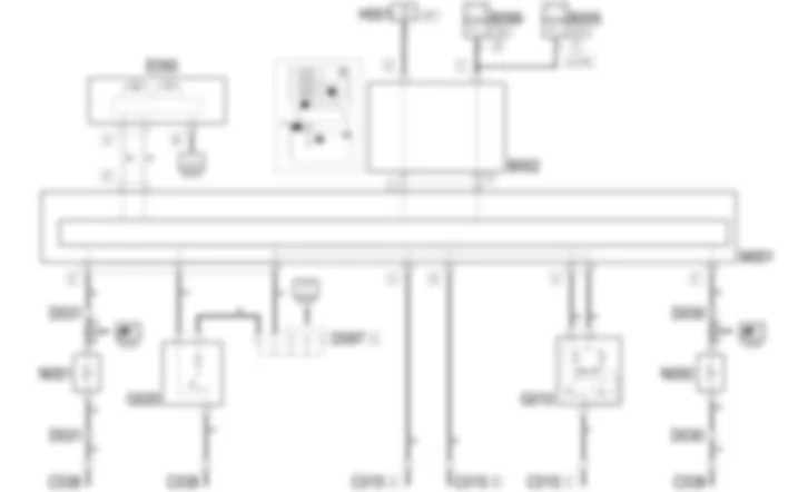
Wiring diagram - COURTESY LIGHTS - Alfa Romeo GT 3.2 V6
Components - COURTESY LIGHTS - Alfa Romeo GT 3.2 V6
| Component code | Name | Assembly reference |
| B1 | JUNCTION UNIT | - |
| B2 | JUNCTION UNIT UNDER DASHBOARD | |
| B5 | MAXI FUSE-1 BOX | - |
| B99 | MAXIFUSE BOX ON BATTERY | |
| C15 | FACIA EARTH, DRIVER''S SIDE | - |
| C38 | EARTH ON TUNNEL | - |
| D30 | REAR COUPLING FOR /FRONT DOOR. DRIVER''S SIDE | - |
| D31 | RIGHT FRONT DOOR REAR COUPLING/. | - |
| D97 | SHORT CIRCUITING COUPLING | - |
| E50 | INSTRUMENT PANEL | |
| G10 | FRONT COURTESY LIGHT ( REAR ) | |
| G20 | REAR COURTESY LIGHT | |
| H1 | IGNITION SWITCH | |
| M1 | BODY COMPUTER | |
| N50 | RIGHT FRONT DOOR LOCK LEFT | |
| N51 | RIGHT FRONT DOOR LOCK MOTOR | |
Location of components - COURTESY LIGHTS - Alfa Romeo GT 3.2 V6
Components - COURTESY LIGHTS - Alfa Romeo GT 3.2 V6
| Component code | Name | Assembly reference |
| B1 | JUNCTION UNIT | - |
| B2 | JUNCTION UNIT UNDER DASHBOARD | |
| B5 | MAXI FUSE-1 BOX | - |
| B99 | MAXIFUSE BOX ON BATTERY | |
| C15 | FACIA EARTH, DRIVER''S SIDE | - |
| C38 | EARTH ON TUNNEL | - |
| D30 | REAR COUPLING FOR /FRONT DOOR. DRIVER''S SIDE | - |
| D31 | RIGHT FRONT DOOR REAR COUPLING/. | - |
| D97 | SHORT CIRCUITING COUPLING | - |
| E50 | INSTRUMENT PANEL | |
| G10 | FRONT COURTESY LIGHT ( REAR ) | |
| G20 | REAR COURTESY LIGHT | |
| H1 | IGNITION SWITCH | |
| M1 | BODY COMPUTER | |
| N50 | RIGHT FRONT DOOR LOCK LEFT | |
| N51 | RIGHT FRONT DOOR LOCK MOTOR | |
Description - COURTESY LIGHTS - Alfa Romeo GT 3.2 V6
The front courtesy light includes two bulbs with two control switches.With the left switch (A) it is possible to select the following two operating modes:centre position: both lights come on for a timed periodleft-hand position: both lights are off all the time;right-hand position: both lights are on all the time.
The right-hand switch turns on only one of the lights:left-hand position: left-hand light always on;right-hand position: right-hand light always on;central position: both lights always off.
The rear courtesy light only has one bulb with different operating modes according to the position of the actual lens cover which operates an internal switch:neutral position: light comes on for a timed period;positioned to one side: lights always off;positioned to the other side: light always on.
The lighting for the two courtesy lights is timed on the basis of a logic managed by the Body Computer.when one of the front doors is opened, the courtesy lights are timed to stay on for 3 minutes;if, whilst opening one door, another is opened, the counting of the three minutes starts again from zero;if a door remains open for longer than three minutes, the courtesy lights go out and remain off until one of the doors is next opened;If, during this period of 3 minutes, all the doors are closed again, a second period of 7 seconds is activated and is interrupted if the ignition key is turned on.when the doors are opened using the remote control, the courtesy lights come on for 15 seconds; the timing is interrupted if the ignition key is turned ON;when the remote control is used to lock the doors, the courtesy lights go off.
The switching off and on should be gradual (dimmer) with a cycle lasting 3 seconds.When the ignition key is turned OFF, the Body Computer checks that the key has actually been removed (no transponder): in these circumstances it switches the front and rear courtesy lights on as described previously.The courtesy lights are also on (without the dimmer) if the inertia switch is operated (the information is sent via the instrument panel CAN).The function is activated with the ignition key in the ON position.The Body Computer continuously acquires the ''battery voltage'' signal and compares it with a limit: if the battery voltage level measured is below this limit, it intervenes through the CAN sending a signal to disable a series of loads: these include the two front and rear courtesy lights; the function is activated with the ignition key in the OFF position.If the Body Computer detects that one of the doors or the boot has been left open and the vehicle speed exceeds around 5 Km/h, a buzzer is sounded.
Functional description - COURTESY LIGHTS - Alfa Romeo GT 3.2 V6
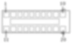
The Body ComputerM1receives the ''door open'' input signals at pin 8 (left door) and pin 25 (right door) of connector E.On the basis of the timing and control logic described previously, the Body Computer M1 supplies the two courtesy lights:from pin 23 of connector E it supplies the front courtesy light G10 ; from pin 21 of the same connector it supplies the earth signal for the timer;from pin 33 of connector E it supplies the rear courtesy light G20 ; from pin 37 of the same connector it supplies the earth signal for the timer;
The Body ComputerM1is connected, via the CAN line, to the instrument panelE50, from which it receives the ''inertia switch operated'' signal which lights up the courtesy lights and sends a signal which, if necessary, can light up the ''doors open'' warning light.The ''low battery voltage'' signal which switches off the courtesy lights if they are on, always arrives via the CAN.Engine compartment junction unit
B1A
B1A
B1A
B1B
B1B
B1B
B1C
B1C
B1C
B1D
B1E
B1E
B1X
B1X
Junction unit under dashboard
B2A
B2A
B2A
B2A
B2A
B2A
B2B
B2B
B2C
B2C
B2D
B2E
B2F
B2G
B2H
MAXI FUSE box
B5A
B5B
B5C
B5D
B5E
B5F
Maxifuse box on battery
B99A
B99A
B99B
B99D
Facia earth, driver's side
C15A
C15B
C15C
Earth on centre tunnel
C38
Rear coupling for front door driver's side
D30
D30
D30
Front passenger door rear coupling
D31
D31
D31
Short circuiting coupling
D97A
D97A
D97A
D97C
D97D
D97E
D97G
D97H
D97I
D97M
Instrument panel
E50A
E50B
Front courtesy light
G10
Rear courtesy light
G20
Ignition switch
H1A
H1A
H1B
Body computer
M1A
M1A
M1A
M1A
M1A
M1A
M1B
M1C
M1D
M1E
M1F
M1G
Front driver's door lock geared motor
N50
Passenger side front door lock geared motor
N51

 English
 English
 Español
 Français
 Nederlands
 Русский

