DEFOGGERS
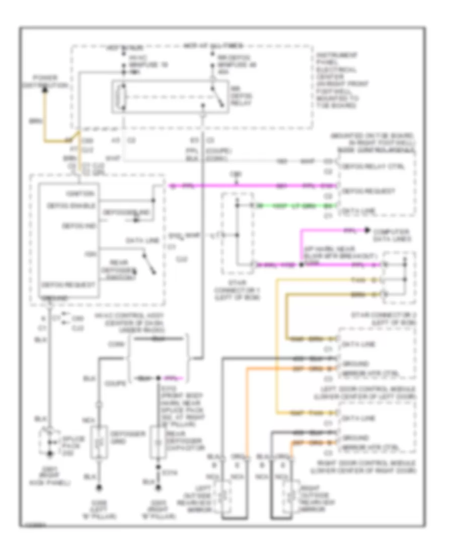
Defogger Wiring Diagram for Chevrolet Corvette 2000
List of elements for Defogger Wiring Diagram for Chevrolet Corvette 2000:
- (conv)
- (i/p harn, near blwr mtr breakout) s206
- (mounted on toe board, in right footwell) body control module
- C1 c1
- C1 k
- C10
- C2 a5
- C60
- Cj2
- Cj2 c60
- Computer data lines
- Conv
- Coupe
- D12
- Data line
- Defog enable
- Defog ind
- Defog relay ctrl
- Defog request
- Defogger grid
- Defogger ind
- E5 c3
- F7 cj2
- G305 (right "b" pillar)
- G308 (left "b" pillar)
- G901 (right kick panel)
- Ground
- Hot at all times
- Hot in run
- Hvac control assy (center of dash, under radio)
- Hvac minifuse 18 10a
- Ign
- Ignition
- Instrument panel electrical center (in right front footwell, mounted to toe board)
- Left door control module (lower center of left door)
- Left outside rearview mirror
- Mirror htr ctrl
- Nca
- Power distribution
- Rear defogger capacitor
- Rear defogger switch
- Right door control module (lower center of right door)
- Right outside rearview mirror
- Rr defog minifuse 48 40a
- Rr defog relay
- S312 (front body harn, near splice pack 302, at right "b" pillar)
- S314
- Splice pack
- Star connector 1 (left of bcm)
- Star connector 2 (left of bcm)
- Tan
 English