
DEFOGGERS
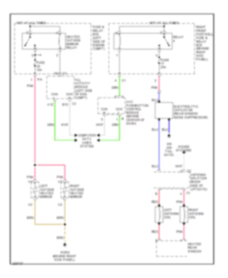
Defoggers Wiring Diagram for Mercedes-Benz ML500 2005
List of elements for Defoggers Wiring Diagram for Mercedes-Benz ML500 2005:
AIR CONDITIONINGBODY CONTROL MODULESCOOLING FANANTI-LOCK BRAKESCOMPUTER DATA LINESDEFOGGERSANTI-THEFTEXTERIOR LIGHTSCRUISE CONTROLGROUND DISTRIBUTIONHORNENGINE PERFORMANCEINTERIOR LIGHTSMEMORY SYSTEMSHEADLIGHTSINSTRUMENT CLUSTERNAVIGATIONPOWER DOOR LOCKSPOWER DISTRIBUTIONPOWER SEATSPOWER MIRRORSRADIOPOWER WINDOWSPOWER TOP/SUNROOFSTARTING/CHARGINGTRANSMISSIONSUPPLEMENTAL RESTRAINTSWIPER/WASHER