DEFOGGERS
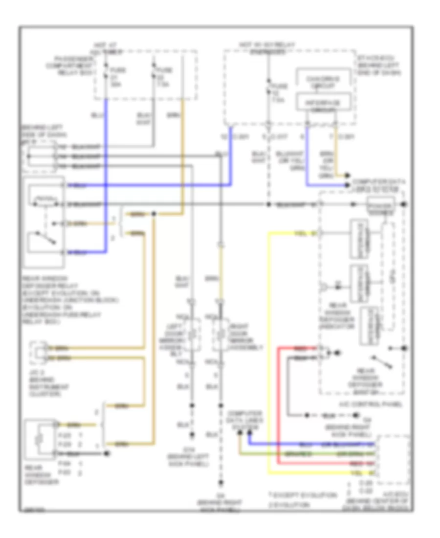
Defoggers Wiring Diagram for Mitsubishi Lancer GTS 2008
List of elements for Defoggers Wiring Diagram for Mitsubishi Lancer GTS 2008:
- (behind left side of dash) j/c 3
- A/c control panel
- A/c-ecu (behind center of dash, below radio)
- C-20
- C-22
- C-301
- C-317
- Can drive circuit
- Computer data lines system
- Cpu
- Etacs-ecu (behind left end of dash)
- Evolution
- Except evolution
- F-03
- F-04
- F-25
- F-29
- Fuse 30a
- Fuse 7.5a
- G14 (behind left kick panel)
- G4 (behind right kick panel)
- Hot at all times
- Hot w/ ig1 relay energized
- Interface circuit
- J/c 2 (behind instrument cluster)
- Left door mirror assem- bly
- Nca
- Passenger compartment relay box
- Power source
- Rear window defogger
- Rear window defogger indicator
- Rear window defogger relay (except evolution: on underdash junction block) (evolution: on underdash fuse/relay relay box)
- Rear window defogger switch
- Red
- Right door mirror assembly
 English