DEFOGGERS
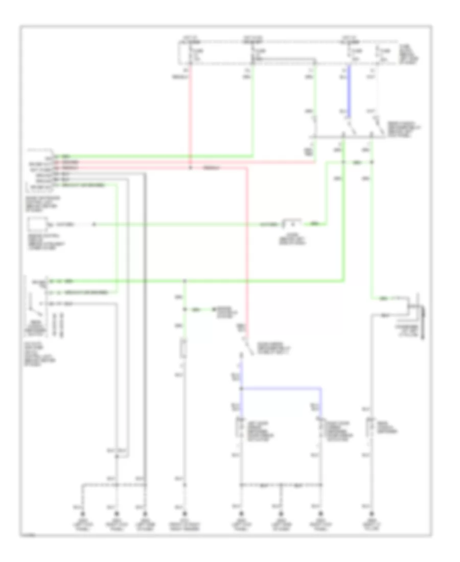
Defogger Wiring Diagram for Nissan Maxima GLE 2001
List of elements for Defogger Wiring Diagram for Nissan Maxima GLE 2001:
- 12l
- A/c auto amplifier (or a/c control unit) (behind center of dash)
- Bat (fuse)
- Condenser (at left "c" pillar)
- Diode (behind left side of dash)
- Door mirror defogger relay (in relay box 1)
- Engine control module (behind intrument lower cover)
- Engine controls system
- Fuse 10a
- Fuse 20a
- Fuse 20a
- Fuse block (behind left side of dash)
- G101 (front of right front fender)
- G200 (left kick panel)
- G202 (left side of dash)
- G203 (right kick panel)
- G905 (right "c" pillar)
- Ground
- Hot at all times
- Hot in on or start
- Ign
- Left door mirror defogger (door mirror actuator)
- Nca
- Rear window defogger
- Rear window defogger relay (behind left kick panel)
- Rear window defogger switch
- Right door mirror defogger (door mirror actuator)
- Rr def f/b
- Rr def out
- Rr def sw
- Smart entrance control unit (behind center of dash)
- W/ auto a/c
- W/o auto a/c
 English