DEFOGGERS
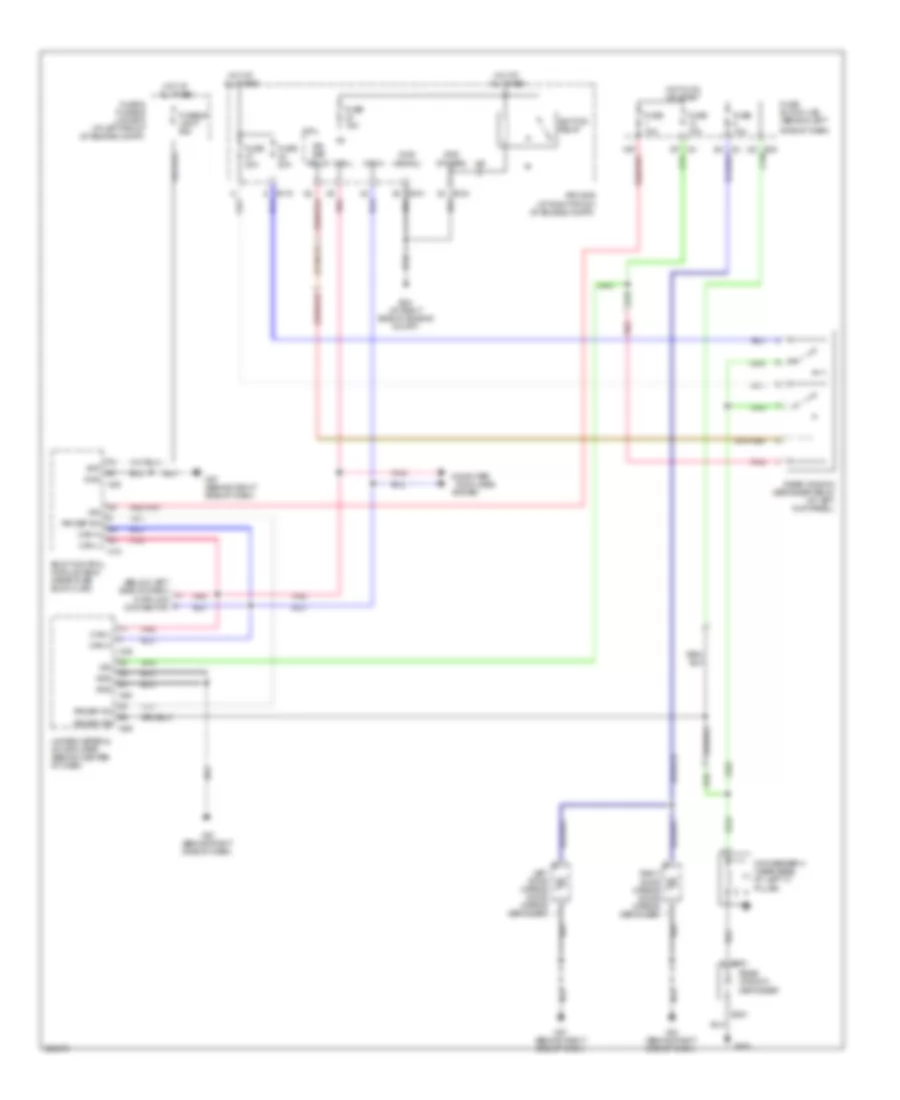
Defoggers Wiring Diagram for Nissan Maxima SL 2007
List of elements for Defoggers Wiring Diagram for Nissan Maxima SL 2007:
- (below left side of dash) data link connector
- + b301
- +ig
- - b351
- 15p
- B352
- Bat
- Body control module (bcm) (near fuse block (j/b))
- Can-h
- Can-l
- Computer
- Condenser-3 (near base of left "c" pillar)
- Cpu
- Data lines
- E119
- E121
- E124
- E24 (at right side of engine compt)
- E30
- Fuse & fusible link box (at left front of engine compt)
- Fuse 10a
- Fuse 15a
- Fuse 20a
- Fuse block (j/b) (behind left
- Fusible link f 50a
- Gnd
- Gnd (power)
- Gnd (signal)
- Hot at all times
- Hot in on or start
- Ign
- Ignition relay
- Ipdm e/r (at right front of engine compt)
- Left door mirror (door mirror defogger)
- M18
- M20
- M49
- M50
- M57 (behind right side of dash)
- M61 (behind right side of dash)
- M89
- Pnk
- Rear window defogger
- Rear window defogger relay (at left kick panel)
- Right door mirror (door mirror defogger)
- Rr def f/b
- Rr def on
- Rr def relay
- Rr def sw
- Side of dash)
- System
- Unified meter & a/c amplifier (behind center of dash)
 English