DEFOGGERS
Defogger Wiring Diagram for Oldsmobile Alero GL 2000
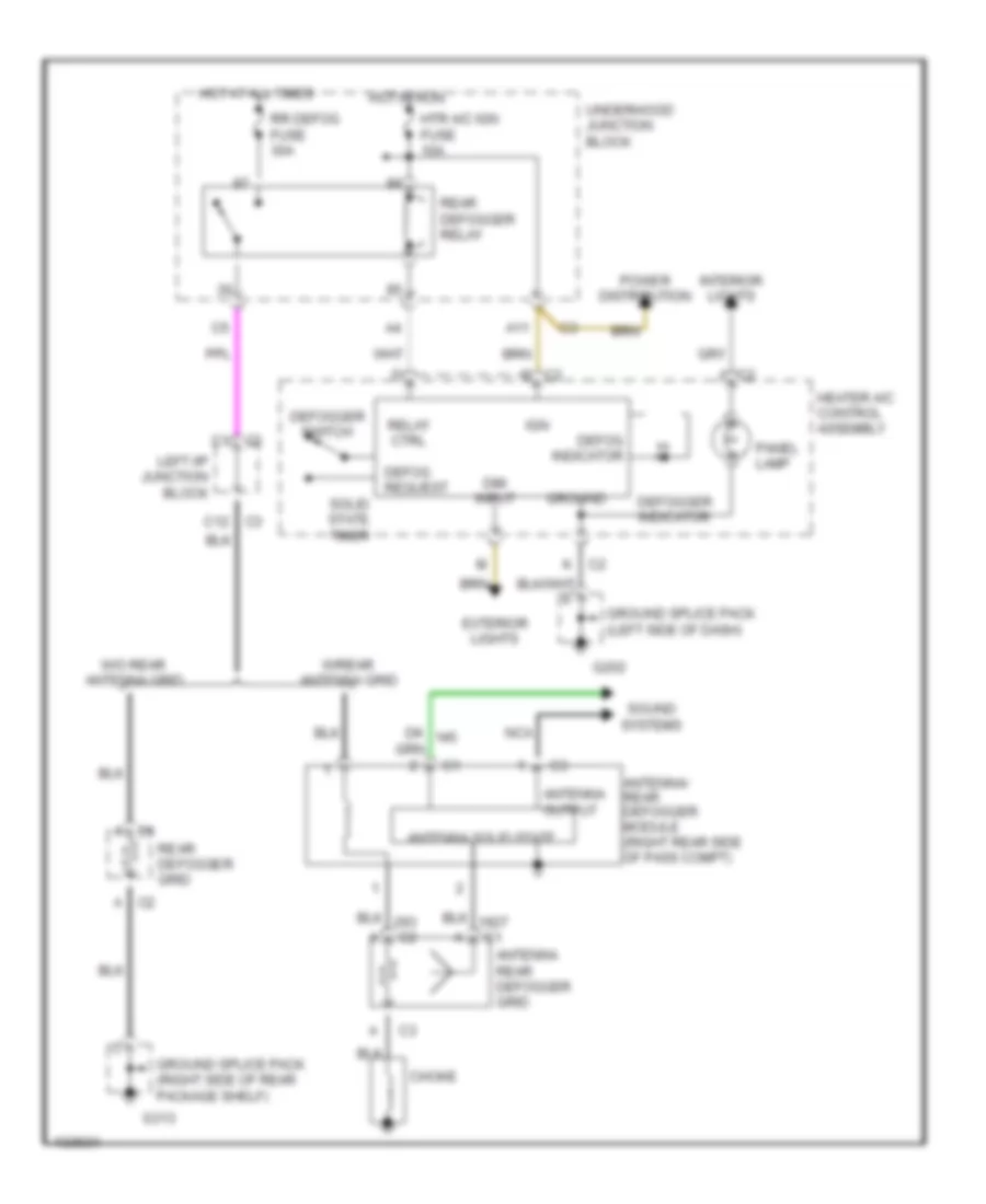
List of elements for Defogger Wiring Diagram for Oldsmobile Alero GL 2000:
- A c1
- A c2
- A11
- Antenna output
- Antenna rear defogger grid
- Antenna solid state
- Antenna/ rear defogger module (right rear side of pass compt)
- C c2
- C1 c2
- C2 j
- C3 c12
- Choke
- Defog indicator
- Defog request
- Defogger indicator
- Defogger switch
- Dim input
- Exterior lights
- G202
- G313
- Ground
- Ground splice pack (left side of dash)
- Ground splice pack (right side of rear package shelf)
- Heater a/c control assembly
- Hot at all times
- Hot in run
- Htr a/c ign fuse 10a
- Ign
- Interior lights
- K c2
- Left i/p junction block
- Nca
- Panel lamp
- Power distribution
- Rear defogger grid
- Rear defogger relay
- Relay ctrl
- Rr defog fuse 30a
- Solid state timer
- Sound systems
- Underhood junction block
- W/o rear antenna grid
- W/rear antenna grid
 English