Dodge Grand Caravan 1992 - 1992 ENGINE PERFORMANCE Self-Diagnostics - 2.5L
Dodge Grand Caravan 1992 - INTRODUCTION
If no faults were found while performing BASIC TESTING , proceed with self-diagnostics. If no fault codes or only pass codes are present after entering self-diagnostics, proceed to appropriate TESTS W/O CODES article in the ENGINE PERFORMANCE Section for diagnosis by symptom (i.e., ROUGH IDLE, NO START, etc.).
Dodge Grand Caravan 1992 - MODEL IDENTIFICATION
Dodge Grand Caravan 1992 VEHICLE BODY IDENTIFICATION
Model Name Body Type Caravan & Voyager AS Dakota AN
Dodge Grand Caravan 1992 - SELF-DIAGNOSTIC SYSTEM
WARNING: When battery is disconnected, vehicle computer and memory systems may lose memory data. Driveability problems may exist until computer systems have completed a relearn cycle. See COMPUTER RELEARN article in the GENERAL INFORMATION Section before disconnecting battery.
Dodge Grand Caravan 1992 - SYSTEM DIAGNOSTICS
The self-diagnostic capabilities of this system, if properly utilized, can simplify testing. The Single Board Engine Controller (SBEC) monitors several different engine control system circuits.
If a problem is sensed with a monitored circuit, SBEC memory stores a fault code, the CHECK ENGINE light glows and SBEC enters limp-in mode. In limp-in mode, SBEC compensates for component failure by substituting information from other sources. This allows vehicle operation until repairs can be made.
Once codes are known, see FAULT CODES table to determine the questionable circuit. Test circuits and repair or replace components as required. If problem is repaired or ceases to exist, the SBEC cancels fault code after 50 ignition on/off cycles. To clear codes, see CLEARING FAULT CODES .
A specific fault code results from a particular system failure. A fault code does not condemn a specific component. Component is not necessarily the reason for failure. Fault codes only call out a probable malfunction area.
Dodge Grand Caravan 1992 - Hard Failures
Hard failures cause CHECK ENGINE light to glow and remain on until the malfunction is repaired. If light comes on and remains on (light may flash) during vehicle operation, cause of malfunction must be determined using self-diagnostic tests. If a sensor fails, SBEC will use a substitute value in its calculations, allowing engine to operate in limp-in mode. In this condition, vehicle will run, but driveability may be poor. DRB-II will display key counter as zero.
Dodge Grand Caravan 1992 - Intermittent Failures
Intermittent failures may cause CHECK ENGINE light to flicker or stay on until the intermittent fault goes away. However, the corresponding fault code will be retained in SBEC memory. If related fault does not reoccur within a certain time frame, related fault code will be erased from SBEC memory. Intermittent failures can be caused by a faulty sensor, bad connector or wiring related problems. DRB-II will display key counter as one or more. See TEST NF-1A in this article or INTERMITTENTS in appropriate TESTS W/O CODES article in the ENGINE PERFORMANCE Section.
Dodge Grand Caravan 1992 - SERVICE PRECAUTIONS
Before proceeding with diagnosis, the following precautions must be followed:
- ALWAYS relieve fuel pressure before disconnecting any fuel injection-related component. DO NOT allow fuel to contact engine or electrical components. See FUEL PRESSURE RELEASE .
- When battery is disconnected, vehicle computer and memory systems may lose memory data. Driveability problems may exist until computer systems have completed a relearn cycle. See COMPUTER RELEARN article in the GENERAL INFORMATION Section before disconnecting battery.
- Vehicle must have a fully charged battery and functional charging system.
- Probe SBEC 60-pin connector from pin side. DO NOT backprobe SBEC connector.
- DO NOT cause short circuits when performing electrical tests. This will set additional fault codes, making diagnosis of original problem more difficult.
- DO NOT use a test light instead of a voltmeter.
- When checking for spark, ensure coil wire is NO more than 1/4" from ground. If coil wire is more than 1/4" from ground, damage to vehicle electronics and/or SBEC may result.
- DO NOT prolong testing of fuel injectors or engine may hydrostatically (liquid) lock.
- Always repair lowest fault code number (CHECK ENGINE light) or first fault displayed (DRB-II) first.
- Always perform VERIFICATION TEST after repairs are made.
- Always disconnect DRB-II after use.
- Always disconnect DRB-II before charging battery.
Dodge Grand Caravan 1992 - VISUAL INSPECTION
Most driveability problems in the engine control system result from faulty wiring, poor electrical connections or leaking air and vacuum hose connections. To avoid unnecessary component testing, perform a visual inspection before beginning self-diagnostic tests.
Dodge Grand Caravan 1992 - DIAGNOSTIC PROCEDURE
NOTE: DO NOT skip any steps in self-diagnostic tests or incorrect diagnosis may result.
Always perform a visual inspection before attempting to diagnose engine control system problems. See VISUAL INSPECTION . Enter on-board diagnostics, and retrieve fault code(s). See ENTERING ON-BOARD DIAGNOSTICS . If fault codes are not present and/or DRB-II (Diagnostic Readout Box-II) is used, proceed to one of the following tests:
- Go to TEST NS-1A - CHECKING FOR FAULTS & SPARK if a no-start condition exists or engine stalls after start-up. Perform indicated VERIFICATION TEST after repairs have been made.
- Go to TEST DR-1A - CHECKING SYSTEM FOR FAULTS if engine runs but has performance problems. Perform indicated VERIFICATION TEST after repairs have been made.
- Go to TEST NF-1A - NO FAULT CODE TEST MENU if a driveability problem exits and no fault codes are present. Perform indicated VERIFICATION TEST after repairs have been made.
Dodge Grand Caravan 1992 - ENTERING ON-BOARD DIAGNOSTICS
NOTE: Although other scan testers are available, manufacturer recommends using DRB-II (Diagnostic Readout Box II) to diagnose the system. CHECK ENGINE light function can be used but has limited diagnostic usage.
Dodge Grand Caravan 1992 - CHECK ENGINE Light Diagnostic Mode
- Start engine (if possible). Move transmission shift lever through all positions, ending in PARK. Turn A/C switch on and then off (if equipped).
- Turn engine off. Without starting engine again, turn ignition on, off, on, off and on. Record 2-digit fault codes as displayed by flashing CHECK ENGINE light.
- For example, Code 23 is displayed as flash, flash, 4-second pause, flash, flash, flash. After a slightly longer pause, other codes stored are displayed in numerical order.
- When CHECK ENGINE light begins to flash fault codes, it cannot be stopped. Start over if count is lost. Code 55 indicates end of fault code display. - FAULT CODES table to translate trouble code number to a system fault description (DRB-II display).
- Once trouble area is identified, refer to appropriate TEST NS-1A (NO-START TEST 1A) or TEST DR-1A (DRIVEABILITY TEST 1A) to diagnose problem. Use self-diagnostic test titles to find appropriate test.
- As an example, a 3.0L engine starts and runs but has a driveability problem. CHECK ENGINE light indicates a Code 14. - FAULT CODES table to translate trouble code number to a system fault description (DRB-II display).
- When system fault description (DRB-II display) is obtained, refer to appropriate TEST DR-1A (DRIVEABILITY TEST DR-1A) since vehicle has a driveability problem. Select fault message and corresponding test from table, and proceed to appropriate test. To clear fault codes, see CLEARING FAULT CODES .
Dodge Grand Caravan 1992 - DRB-II Diagnostic Mode
- Turn ignition off. Connect DRB-II to engine diagnostic connector. Engine diagnostic connector is located in engine compartment, near SBEC on all models except Dakota. On Dakota models, diagnostic connector is located in right rear corner of engine compartment, taped to harness.
- Start engine (if possible). With foot on brake, move transmission shift lever through all positions, ending in PARK. Turn A/C switch on and then off (if equipped).
- Turn engine off. Without starting engine again, turn ignition on. Enter FUEL/IGN MENU. To enter FUEL/IGN MENU, see FUEL/IGN MENU under DRB-II TEST FUNCTIONS. At FUEL/IGN MENU, press "2" (READ FAULTS) key. Press ENTER key. After fault codes are accessed, see appropriate TEST NS-1A (NO-START TEST 1A) or TEST DR-1A (DRIVEABILITY TEST 1A) to diagnose problem.
- To erase fault codes while in this mode, press ATM key. At DRB-II display, press "2" (ERASE) key. DRB-II will display ERASE FAULTS ARE YOU SURE? (ENTER TO ERASE). Press ENTER key.
- When DRB-II is finished erasing fault codes, it will display FAULTS ERASED. This display will remain until ATM key is pressed. After ATM key is pressed, display will return to FUEL/IGN MENU screen.
Dodge Grand Caravan 1992 - CLEARING FAULT CODES
NOTE: Fault codes can also be cleared in READ FAULTS mode of DRB-II. To ensure all faults are read, use READ FAULTS mode to erase fault codes. See DRB-II DIAGNOSTIC MODE under ENTERING ON-BOARD DIAGNOSTICS .
- If DRB-II is not available, go to step 3). If DRB-II is available, enter FUEL/IGN MENU. See FUEL/IGN MENU under DRB-II TEST FUNCTIONS. At FUEL/IGN MENU, press "5" (ADJUSTMENTS) key. Press ENTER key. At ADJUSTMENTS menu, press "1" (ERASE FAULTS) key. Press ENTER key.
- DRB-II will display ERASE FAULTS ARE YOU SURE? (ENTER TO ERASE). Press ENTER key. When DRB-II is finished erasing fault codes, screen will display FAULTS ERASED.
- If DRB-II is not available, fault codes may be cleared by disconnecting negative battery cable for at least 15 seconds, allowing SBEC to clear fault codes.
Dodge Grand Caravan 1992 - SUMMARY
If no hard fault codes (or only pass codes) are present, driveability symptoms exist or intermittent codes exist, proceed to appropriate TESTS W/O CODES article in the ENGINE PERFORMANCE Section for diagnosis by symptom (i.e., ROUGH IDLE, NO START, etc.) or intermittent diagnostic procedures.
Dodge Grand Caravan 1992 - DTC & FAULT CODES/MESSAGES FAULT CODES/MESSAGES (Note: For DTC table, see TEST FC-1A under "Testing.")
Dodge Grand Caravan 1992 FAULT CODES
Code Display On DRB-II (1) Fault Condition 11 NO REFERENCE SIGNAL DURING CRANKING No Distributor Reference Signal Detected During Cranking. 13 SLOW CHANGE IN IDLE MAP SIGNAL MAP Output Change Is Slower And/Or Smaller Than Expected. " NO CHANGE IN MAP FROM START TO RUN No Difference Recognized Between MAP Reading And Barometric (Atmospheric) Pressure Reading At Start-Up. 14 MAP VOLTAGE TOO LOW MAP Sensor Input Less Than Minimum Acceptable Voltage. 14 MAP VOLTAGE TOO HIGH MAP Sensor Input More Than Maximum Acceptable Voltage. 15 NO VEHICLE SPEED SIGNAL No Distance Sensor Signal Detected During Road Load Conditions. 17 ENGINE COLD TOO LONG Coolant Temperature Stays Less Than Normal Operating Temperature During Vehicle Operation. 21 O2 SIGNAL STAYS AT CENTER No Rich Or Lean Signal Is Detected From O2 Sensor Input. 21 O2 SIGNAL SHORTED TO VOLTAGE O2 Sensor Input Voltage Maintained At More Than Normal Operating Range. 22 COOLANT SENSOR VOLTAGE TOO LOW Coolant Temperature Sensor Input Less Than Minimum Acceptable Voltage. 22 COOLANT SENSOR VOLTAGE TOO HIGH Coolant Temperature Sensor Input More Than Maximum Acceptable Voltage. 23 THROTTLE BODY TEMP VOLTAGE LOW Throttle Body Temperature Sensor Input Less Than Minimum Acceptable Voltage. 23 THROTTLE BODY TEMP VOLTAGE HIGH Throttle Body Temperature Sensor Input More Than Maximum Acceptable Voltage. 24 TPS VOLTAGE LOW TPS Sensor Input Less Than Minimum Acceptable Voltage. 24 TPS VOLTAGE HIGH TPS Sensor Input More Than Maximum Acceptable Voltage. 25 AIS MOTOR CIRCUITS Open Or Shorted Condition Detected In One Or More Auto Idle Speed (AIS) Control Circuits. 27 INJECTOR CONTROL CIRCUIT Injector Output Driver Does Not Respond Properly To SBEC Control Signal. 31 PURGE SOLENOID CIRCUIT Open Or Shorted Condition Is Detected In Purge Solenoid Circuit. 32 EGR SOLENOID CIRCUIT Open Or Shorted Condition Is Detected In Egr Solenoid Circuit. 32 EGR SYSTEM FAILURE SBEC Did Not Detect Required Air/Fuel Change During Diagnostic Test. 33 A/C CLUTCH RELAY CIRCUIT Open Or Shorted Condition Detected In A/C Clutch Relay Circuit. 34 S/C SOLENOIDS CIRCUIT Open Or Shorted Condition Detected In Speed Control (S/C) Vacuum Or Vent Solenoid Circuits. 35 RADIATOR FAN RELAY CIRCUIT Open Or Shorted Condition Detected In Radiator Fan Relay Circuit. 37 TORQUE CONVERTER LOCK-UP SOLENOID CIRCUIT Open Or Shorted Condition Detected In Torque Converter Lock-Up Solenoid Circuit. 41 (2) ALTERNATOR FIELD NOT SWITCHING PROPERLY Alternator Field Not Switching Properly. 42 ASD RELAY CONTROL CIRCUIT Open Or Shorted Condition Detected In ASD Relay Circuit. 42 NO ASD RELAY VOLTAGE SENSED AT CONTROLLER No ASD Relay Voltage Sensed When ASD Relay Is Energized. 44 (2) BATTERY TEMP VOLTAGE Open Or Shorted Condition Exists In Coolant Temperature Sensor Circuit Or In SBEC Battery Temperature Voltage Circuit. 46 (2) CHARGING VOLTAGE TOO HIGH Charging System Voltage Too High. 47 (2) CHARGING VOLTAGE TOO LOW Charging System Voltage Too Low. 51 O2 SIGNAL STAYS BELOW CENTER (LEAN) O2 Sensor Input Indicates Lean Air/Fuel Ratio During Engine Operation. " ADDITIVE ADAPTIVE MEMORY AT RICH LIMIT Additive Adaptive Memory At Rich Limit. 52 O2 SIGNAL STAYS ABOVE CENTER (RICH) O2 Sensor Input Indicates Rich Air/Fuel Ratio During Engine Operation. " ADDITIVE ADAPTIVE MEMORY AT LEAN LIMIT Additive Adaptive Memory At Lean Limit. 55 (NO DISPLAY ON DRB-II) Completion Of Fault Code Display By CHECK ENGINE Light. 62 CONTROLLER FAILURE EMR MILES NOT STORED Unsuccessful Attempt To Update EMR Mileage In SBEC. 63 CONTROLLER FAILURE EEPROM WRITE DENIED Unsuccessful Attempt To Write To An EEPROM Location By SBEC.
(1) Actual message displayed on DRB-II may vary between vehicles.
(2) If code is displayed, charging system malfunction exists. See appropriate ALTERNATOR & REGULATOR article in ELECTRICAL Section.
Dodge Grand Caravan 1992 - DRB-II TEST FUNCTIONS
WARNING: When battery is disconnected, vehicle computer and memory systems may lose memory data. Driveability problems may exist until computer systems have completed a relearn cycle. See COMPUTER RELEARN article in the GENERAL INFORMATION Section before disconnecting battery.
Dodge Grand Caravan 1992 - FUEL/IGN MENU
NOTE: DO NOT touch DRB-II keypad during DRB-II power-up sequence or an error message will result.
- In order to perform self-diagnostic tests using DRB-II, DRB-II must be in the FUEL/IGN MENU. At the FUEL/IGN MENU, fault codes and DRB-II test functions can be accessed.
- To reach FUEL/IGN MENU, turn ignition off. Connect DRB-II to engine diagnostic connector, located in engine compartment, near SBEC on all models except Dakota. On Dakota models, diagnostic connector is located in right rear corner of engine compartment, taped to harness. Turn ignition switch to RUN position.
- All DRB-II character positions will glow and copyright information will appear on screen for a few seconds. If screen is blank or any error messages appear, see DRB-II PROBLEMS & ERROR MESSAGES .
- After a few seconds, DRB-II menu will appear. At DRB-II menu, press "4" (SELECT SYSTEM) key. Press ENTER key. At SELECT SYSTEM menu, press "1" (ENGINE) key. Press ENTER key. DRB-II screen will indicate engine year, size, type of transmission and SBEC part number.
- After a few seconds, AIR COND menu will appear. Press "1" (WITH A/C) or "2" (WITHOUT A/C). DRB-II display will change to ENGINE SYSTEMS menu. At ENGINE SYSTEMS menu, press "1" (FUEL/IGNITION) key. Press ENTER key.
- Display will change to FUEL/IGN MENU. At FUEL/IGN MENU of engine diagnostic program, specific test functions programmed into DRB-II can be performed. The following DRB-II modes can be accessed: SYSTEM TESTS, READ FAULTS, STATE DISPLAY, ACTUATOR TESTS and ADJUSTMENTS.
Dodge Grand Caravan 1992 - SYSTEM TESTS Mode
This mode is not available in the engine diagnostics program.
Dodge Grand Caravan 1992 - READ FAULTS Mode
This mode allows user to read and erase fault codes. A fault counter will appear along with fault displayed. As an example, DRB-II will display 1 OF 2 FAULTS. SBEC will store up to 8 fault messages. Faults are numbered in reverse order of setting. The most recent fault to occur will be displayed first. Vehicles without air conditioning will always have A/C CLUTCH RELAY CKT (circuit) stored in memory. This fault will always be displayed first if vehicle is not equipped with A/C. If no fault messages are stored, DRB-II will display NO FAULTS DETECTED and start counter will show 0 STARTS SINCE ERS (erased).
A start counter will appear below DRB-II fault counter display. Start counter counts the number of times vehicle is started since faults were last set or erased or battery was disconnected. This helps determine if fault is intermittent. Memory space limits start counter to first 3 faults. Start counter of zero equals a hard fault. Start counter of more than zero indicates an intermittent fault. Start counter will count up to 255 starts. If no fault messages are stored, DRB-II will display NO FAULTS DETECTED and start counter will show 0 STARTS SINCE ERS (erased).
Dodge Grand Caravan 1992 - STATE DISPLAY Mode
This mode provides access to FUEL/IGN STATE menu. FUEL/IGN STATE menu permits viewing groups of data regarding the SBEC, sensor and switch inputs, controlled outputs, and predetermined or user selectable groups of data. The following modes can be accessed from the FUEL/IGN STATE menu: MODULE INFO, SENSORS, INPUTS/OUTPUTS, MONITORS and CUSTOM DISPLAYS. For information about the function of these modes, see FUEL/IGN STATE MENU.
Dodge Grand Caravan 1992 - ACTUATOR TESTS Mode
This mode allows the user to check for proper operation of output circuits or devices which the SBEC cannot internally recognize. DRB-II allows SBEC to activate these outputs or devices, allowing an observer to verify proper operation.
Most of the tests available in this mode provide an audible or visual indication of device operation (click of relay contacts, spray fuel, etc.). With the exception of an intermittent condition, if a device functions properly during its test, the device, wiring and its driver circuit are presumably functioning properly.
Dodge Grand Caravan 1992 - ADJUSTMENTS Mode
This mode allows the opportunity to make adjustments to SBEC memory. The following modes can be accessed from the ADJUSTMENTS menu: ERASE FAULTS, RESET MEMORY and EMR MEMORY CHECK. For information about the function of these modes, see ADJUSTMENTS MENU.
Dodge Grand Caravan 1992 - ADJUSTMENTS MENU ERASE FAULTS Mode
This mode erases fault messages which are stored in SBEC memory. Once this mode is selected, DRB-II displays ARE YOU SURE? If fault erasure is not desired, press ATM key. If fault erasure is desired, press ENTER key. All faults and secondary indicators will be erased.
Dodge Grand Caravan 1992 - RESET MEMORY Mode
This mode provides a sub-menu listing resettable memories. As vehicle is operated, SBEC learns to adjust fuel delivery, automatic idle speed motor position and minimum throttle position sensor signal voltage to compensate for different engine operating conditions. The following modes can be accessed from the RESET MEMORY menu: ADAPTIVE FUEL, AIS COUNTER, MINIMUM TPS and ALL VALUES. For additional information about the function of these modes, see RESET MEMORY MENU .
Dodge Grand Caravan 1992 - EMR MEMORY CHECK Mode
This mode allows the user to check and correct mileage stored in SBEC (if necessary). See EMISSION MAINTENANCE REMINDER (EMR) MILEAGE TRANSFER .
Dodge Grand Caravan 1992 - FUEL/IGN STATE MENU MODULE INFO Mode
Mode displays model year, engine displacement, emission type, transmission type and SBEC part number.
Dodge Grand Caravan 1992 - SENSORS Mode
This mode provides a list of sensors and their input value to the SBEC.
Dodge Grand Caravan 1992 - INPUTS/OUTPUTS Mode
This mode provides a list of input switch and output device circuits and status.
Dodge Grand Caravan 1992 - MONITORS Mode
This mode provides access to MONITORS menu. MONITORS menu displays up to 12 inputs and outputs relating to a specific area of fuel and ignition system performance. The following modes can be accessed from the MONITORS menu: FUEL CONTROL, ADVANCE, RPM, ADAPTIVE MEM, NO START, INTERROGATOR and SEC INDICATORS. For additional information about the function of these modes, see MONITORS MENU .
Dodge Grand Caravan 1992 - CUSTOM DISPLAYS Mode
This mode allows the user to customize DRB-II display. The user can select up to 4 different displays which can be shown on a single screen. Any item from inputs/output list, sensor list or actuator list can be selected from custom display. Once selected, custom display will be retained in memory until changed. Up to 2 custom display screens can be customized by user.
Dodge Grand Caravan 1992 - MONITORS MENU FUEL CONTROL Mode
This mode allows the user to display inputs and outputs which affect fuel delivery.
Dodge Grand Caravan 1992 - ADVANCE Mode
This mode allows the user to display inputs and outputs which affect ignition timing advance.
Dodge Grand Caravan 1992 - RPM Mode
This mode allows the user to display inputs and outputs which affect engine speed.
Dodge Grand Caravan 1992 - ADAPTIVE MEM Mode
This mode allows the user to display inputs and outputs which affect adaptive memory. As a vehicle is operated, SBEC learns to adjust fuel delivery, automatic idle speed motor position and minimum throttle position sensor signal voltage to compensate for different engine operating conditions.
Dodge Grand Caravan 1992 - NO START Mode
This mode allows user to display inputs and outputs which affect engine starting.
Dodge Grand Caravan 1992 - INTERROGATOR Mode
This mode displays selectable inputs and outputs for use during the engineering process. This mode is not available in the engine diagnostics program.
Dodge Grand Caravan 1992 - SEC INDICATORS Mode
This mode allows user to display inputs and outputs which are not within optimum parameters but have not yet become faults. Secondary indicators are monitored by the DRB-II at all times after engine is selected in SELECT SYSTEM menu. When a secondary indicator is generated, DRB-II will emit 5 short beeps. If a secondary indicator becomes a hard fault, DRB-II red LED (light emitting diode) will glow.
Dodge Grand Caravan 1992 - RESET MEMORY MENU ADAPTIVE FUEL Mode
This mode allows the user to erase SBEC memory of learned fuel delivery. As a vehicle is operated, SBEC learns to adjust fuel delivery, automatic idle speed motor position and minimum throttle position sensor signal voltage to compensate for different engine operating conditions.
Dodge Grand Caravan 1992 - AIS COUNTER Mode
This mode allows the user to erase SBEC memory of start-up Automatic Idle Speed (AIS) motor steps.
Dodge Grand Caravan 1992 - MINIMUM TPS Mode
This mode allows the user to erase SBEC memory of lowest Throttle Position Sensor (TPS) voltage.
Dodge Grand Caravan 1992 - ALL VALUES Mode
This mode allows the user to erase SBEC memory of adaptive fuel delivery, automatic idle speed motor position and minimum throttle position sensor signal voltage.
Dodge Grand Caravan 1992 - DRB-II VOLT/OHMMETER
- To access volt/ohmmeter mode of DRB-II, connect Red volt/ohmmeter test lead to Red port, located on right top side of DRB-II.
NOTE: Because DRB-II is grounded through engine diagnostic connector, only one volt/ohmmeter test lead is required when using volt/ohmmeter option. DRB-II volt/ohmmeter should only be used when self-diagnostic tests require the use of this option. - To access voltmeter, press VOLT/OHM key once. DRB-II is now in voltmeter mode. Touch test probe to connector or wire to be measured. Read voltage on DRB-II display. When voltage testing is complete, press VOLT/OHM key 3 times to exit voltmeter mode.
- To access ohmmeter, press VOLT/OHM key twice. DRB-II is now in ohmmeter mode. Touch test probe to connector or wire to be measured. Read resistance to circuit ground on DRB-II display. When resistance testing is complete, press VOLT/OHM key twice to exit ohmmeter mode.
Dodge Grand Caravan 1992 - DRB-II Continuity Meter Mode
Press VOLT/OHM key 3 times. Display will read NO CONTINUITY. Touch test probe to connector or wire to be measured. Read continuity on DRB-II display. When continuity testing is complete, press VOLT/OHM key once to exit continuity meter mode.
Dodge Grand Caravan 1992 - DRB-II PROBLEMS & ERROR MESSAGES Blank Message Screen
- Connect DRB-II to a different vehicle. If message screen is still blank, DRB-II or cable adapter is faulty. Substitute to find faulty component.
- If message screen is not blank, DRB-II and cable adapter are functioning properly. Inspect diagnostic connector for proper wire placement, damaged terminals and pushed-out pins. Repair as necessary.
- If engine diagnostic connector is okay, check for continuity between Black/tracer wire (tracer color may vary) and ground at engine diagnostic connector using an ohmmeter. If continuity does not exist, repair open in Black/tracer wire.
Dodge Grand Caravan 1992 - NO RESPONSE Message
- Connect DRB-II to another vehicle. If DRB-II displays NO RESPONSE message again, DRB-II or cable adapter are faulty. Substitute to find faulty component. If message screen does not display NO RESPONSE, DRB-II and cable adapter are functioning properly. Go to next step.
- Turn ignition off. Disconnect DRB-II. Using an ohmmeter, check Pink wire for continuity between SBEC connector terminal No. 25 and engine diagnostic connector. Check Pink wire for a short to ground. If continuity does not exist or wire is shorted to ground, repair open/shorted in Pink wire.
- If continuity exists and wire is not shorted to ground, check Light Green wire for continuity between SBEC connector terminal No. 45 and engine diagnostic connector. Check Light Green wire for a short to ground. If continuity does not exist or wire is shorted to ground, repair open/shorted in Light Green wire. If all systems check okay, replace SBEC. Reset EMR mileage.
Dodge Grand Caravan 1992 - Other Failure Messages
If BAD FRAMING, CARTRIDGE ERROR, LOW BATTERY, BAD OP CODE, HIGH BATTERY, RAM TEST FAILURE, COMMAND REJECTED or KEYPAD TEST FAILURE Message is displayed, see G - BODY TESTS W/CODES article in the ENGINE PERFORMANCE Section.
Dodge Grand Caravan 1992 - EMISSION MAINTENANCE REMINDER (EMR) MILEAGE TRANSFER
- When SBEC is replaced, vehicle mileage must be copied from odometer to replacement SBEC memory. Transfer of vehicle mileage will enable new SBEC to operate EMR light properly.
- Using DRB-II, enter FUEL/IGN MENU. See DRB-II TEST FUNCTIONS. At FUEL/IGN menu, press "5" (ADJUSTMENTS) key. Press ENTER key. At ADJUSTMENTS menu, press "3" (EMR MEMORY CHECK) key. Press ENTER key. DRB-II will display EMR MEMORY CHECK ARE YOU SURE? ENTER TO CONTINUE.
- Press ENTER key. DRB-II will display IS INSTRUMENT PANEL MILEAGE BETWEEN XXXXX AND XXXXX? If vehicle mileage is within specification, EMR memory check is complete. Press YES key. If vehicle mileage is not within specification, go to next step.
- Press NO key. DRB-II will display ENTER MILEAGE SHOWN ON INSTRUMENT PANEL, USE ENTER KEY TO END. Enter vehicle mileage. DO NOT enter tenths. When correct vehicle mileage is entered, press ENTER key.
- DRB-II will ask for verification of mileage entry. If mileage entry was accurate, press ENTER key. DRB-II will display EMR MEMORY CHECK TEST COMPLETE. Vehicle must travel at least 8 miles for reset to occur.
Dodge Grand Caravan 1992 - FUEL PRESSURE RELEASE RELIEVING FUEL PRESSURE
WARNING: Always relieve fuel pressure before disconnecting any fuel injection-related component. DO NOT allow fuel to contact engine or electrical components.
- Slowly open fuel tank cap to release pressure in tank. To release remaining pressure in system, disconnect injector wiring harness connector. Ground injector harness connector terminal No. 1 using jumper wire. See Fig. 1 .
- Using a second jumper wire, apply battery voltage to injector harness connector terminal No. 2. DO NOT apply battery voltage to terminal No. 2 for more than 5 seconds. Remove jumper wires. Connect injector wiring harness connector. Fuel pressure is now fully released.
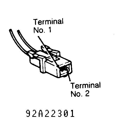
Fig. 1: Dodge Grand Caravan 1992 - Component Locations - Injector Harness Connector Terminal ID
Dodge Grand Caravan 1992 - CONNECTOR IDENTIFICATION
WARNING: When battery is disconnected, vehicle computer and energy systems may lose memory data. Driveability problems may exist until computer systems have completed a relearn cycle. See COMPUTER RELEARN article in the GENERAL INFORMATION Section before disconnecting battery.
Dodge Grand Caravan 1992 CONNECTOR IDENTIFICATION DIRECTORY
Connector See
Fig.re Automatic Idle Speed (AIS) Motor Fig. 2 Coolant Temperature Sensor Fig. 3 Distance Sensor Fig. 4 Distributor Pick-Up Fig. 5 EGR Solenoid Fig. 6 Engine Diagnostic Fig. 7 Fuel Injector Fig. 8 Fuel Pump Fig. 9 Ignition Coil Fig. 10 Manifold Absolute Pressure (MAP) Sensor Fig. 11 Oil Pressure Switch Fig. 12 Oxygen (O2) Sensor Fig. 13 Purge Solenoid Fig. 14 Relays AS Body: A/C Clutch, A/C Fan, Auto Shutdown, Fuel Pump & Radiator Fan Relays Fig. 15 AN Body: A/C Clutch, Auto Shutdown, Fuel Pump & Radiator Fan Relays Fig. 16 Single Board Engine Controller (SBEC) Fig. 17 Throttle Body Charge Temperature Sensor Fig. 18 Throttle Position Sensor (TPS) Fig. 19 Torque Converter Lock-Up Solenoid Fig. 20
Dodge Grand Caravan 1992 - AUTOMATIC IDLE SPEED (AIS) MOTOR CONNECTOR

Dodge Grand Caravan 1992 - COOLANT TEMPERATURE SENSOR CONNECTOR

Dodge Grand Caravan 1992 - DISTANCE SENSOR CONNECTOR
Fig. 4: Dodge Grand Caravan 1992 - Component Locations - Distance Sensor Connector Terminal ID

Dodge Grand Caravan 1992 - DISTRIBUTOR PICK-UP CONNECTOR
Fig. 5: Dodge Grand Caravan 1992 - Component Locations - Distributor Pick-Up Connector Terminal ID

Dodge Grand Caravan 1992 - EGR SOLENOID CONNECTOR
Fig. 6: Dodge Grand Caravan 1992 - Component Locations - EGR Solenoid Connector Terminal ID

Dodge Grand Caravan 1992 - ENGINE DIAGNOSTIC CONNECTOR
Fig. 7: Dodge Grand Caravan 1992 - Component Locations - Engine Diagnostic Connector Terminal ID

Dodge Grand Caravan 1992 - FUEL INJECTOR CONNECTOR
Fig. 8: Dodge Grand Caravan 1992 - Component Locations - Fuel Injector Connector Terminal ID

Dodge Grand Caravan 1992 - FUEL PUMP HARNESS CONNECTOR
Fig. 9: Dodge Grand Caravan 1992 - Component Locations - Fuel Pump Harness Connector Terminal ID

Dodge Grand Caravan 1992 - IGNITION COIL CONNECTOR
Fig. 10: Dodge Grand Caravan 1992 - Component Locations - Ignition Coil Connector Terminal ID

Dodge Grand Caravan 1992 - MANIFOLD ABSOLUTE PRESSURE (MAP) SENSOR CONNECTOR
Fig. 11: Dodge Grand Caravan 1992 - Component Locations - MAP Sensor Connector Terminal ID

Dodge Grand Caravan 1992 - OIL PRESSURE SWITCH CONNECTOR
Fig. 12: Dodge Grand Caravan 1992 - Component Locations - Oil Pressure Switch Connector Terminal ID

Dodge Grand Caravan 1992 - OXYGEN (O2) SENSOR CONNECTOR
Fig. 13: Dodge Grand Caravan 1992 - Component Locations - Oxygen (O2) Sensor Connector Terminal ID

Dodge Grand Caravan 1992 - PURGE SOLENOID CONNECTOR
Fig. 14: Dodge Grand Caravan 1992 - Component Locations - Purge Solenoid Connector Terminal ID

Dodge Grand Caravan 1992 - RELAY CONNECTOR (AS BODY)
Fig. 15: Dodge Grand Caravan 1992 - Component Locations - Relay Connector Terminal ID (AS Body)

Dodge Grand Caravan 1992 - RELAY CONNECTOR (AN BODY)
Fig. 16: Dodge Grand Caravan 1992 - Component Locations - Relay Connector Terminal ID (AN Body)

Dodge Grand Caravan 1992 - SINGLE BOARD ENGINE CONTROLLER (SBEC) CONNECTOR
Fig. 17: Dodge Grand Caravan 1992 - Component Locations - SBEC Connector Terminal ID

Dodge Grand Caravan 1992 - THROTTLE BODY CHARGE TEMPERATURE SENSOR CONNECTOR (AN BODY)

Dodge Grand Caravan 1992 - THROTTLE POSITION SENSOR CONNECTOR

Dodge Grand Caravan 1992 - TORQUE CONVERTER LOCK-UP SOLENOID CONNECTOR

Dodge Grand Caravan 1992 - SELF-DIAGNOSTIC TESTS
NOTE: In the following self-diagnostic tests, illustrations are courtesy of Chrysler Motors.
Dodge Grand Caravan 1992 - TEST NS-1A - CHECKING FOR FAULTS & SPARK
NOTE: For connector terminal identification, see CONNECTOR IDENTIFICATION . For wiring diagram, see appropriate WIRING DIAGRAMS at end of article.
- Ensure battery is fully charged. Disconnect and reconnect battery quick disconnect cable. Try to start engine by cranking for at least 10 seconds. Ensure ignition is turned off before each attempt to start engine. Turn ignition switch to ON position. Read faults using DRB-II. See DRB-II FAULT MESSAGES table.
Dodge Grand Caravan 1992 DRB-II FAULT MESSAGES
DTC DRB-II Message Test No. Code 25 AUTOMATIC IDLE SPEED MOTOR CIRCUITS NS-6A Code 42 AUTO SHUTDOWN RELAY CONTROL CIRCUIT NS-10A Code 53 CONTROLLER FAILURE SPI COMMUNICATIONS (1) Code 22 & 24 COOLANT VOLTAGE & TPS VOLTAGE HIGH (2) Code 27 INJECTOR NO. 1 CONTROL CIRCUIT NS-5A Code 53 INTERNAL CONTROLLER FAILURE (1) Code 42 NO ASD RELAY VOLTAGE SENSE AT CONTROLLER NS-11A Code 11 NO REFERENCE SIGNAL DURING CRANKING NS-9A NO RESPONSE NS-8A (1) Replace SBEC. Perform VERIFICATION TEST VER-1 . (2) Repair open Black/Light Blue wire at SBEC connector terminal No. 4. Perform VERIFICATION TEST VER-1 . - If no faults are displayed, try to start engine by cranking for at least 10 seconds. Ensure ignition is turned off before each attempt to start engine. If engine starts then stalls, perform TEST NS-2A. If engine does not start, go to next step.
CAUTION: When checking for spark, Single Board Engine Controller (SBEC) damage may occur if spark plug cable is held more than 1/4" away from a good ground. - Turn ignition switch to OFF position. Disconnect any spark plug wire at spark plug. Insert an insulated screwdriver in wire terminal. Hold screwdriver a maximum of 1/4" away from a good ground. Watch for spark while cranking engine for 10 seconds. If a good spark occurs, perform TEST NS-2A - CHECKING FUEL SYSTEM . If a good spark does not occur, go to next step.
- Turn ignition switch to OFF position. Reconnect spark plug wire. Disconnect coil wire from distributor. Hold coil wire a maximum of 1/4" away from a good ground. Watch for spark while cranking engine for 10 seconds. If a good spark does not occur, go to next step. If a good spark occurs, repair secondary ignition circuit (distributor cap, rotor and spark plug wires). Perform VERIFICATION TEST VER-1 .
- Turn ignition switch to OFF position. Remove coil wire. Using an external ohmmeter, check coil wire resistance. If resistance is more than 15,000 ohms, go to next step. If resistance is less than 15,000 ohms, replace coil wire. Perform VERIFICATION TEST VER-1 .
- Remove distributor cap. Crank engine and check if distributor rotor turns. If rotor turns, install distributor cap, and go to next step. If rotor does not turn, repair distributor drive components. Perform VERIFICATION TEST VER-1 .
- Disconnect ignition coil connector. Using DRB-II, actuate fuel system. Place DRB-II in voltmeter mode. Connect probe to Dark Green/Black wire at coil connector.
- Go to next step if voltage is more than 10 volts. If voltage is less than 10 volts, repair Dark Green/Black wire between coil and Auto Shutdown (ASD) relay. Perform VERIFICATION TEST VER-1 .
- Connect probe to Black/Gray wire at coil connector. Go to next step if voltage is less than 10 volts. Go to step 12 if voltage is more than 10 volts.
- Turn ignition switch to OFF position. Disconnect Single Board Engine Controller (SBEC) connector. Place DRB-II in ohmmeter mode. Connect ohmmeter probe to terminal No. 19 (Black/Gray wire) at SBEC connector. If resistance is less than 10 ohms, go to next step. If resistance is more than 10 ohms, repair short to ground in ignition coil circuit. Perform VERIFICATION TEST VER-1 .
- Check resistance at Black/Gray wire between coil connector and terminal No. 19 at SBEC connector using an external ohmmeter. Replace SBEC if resistance is more than 10 ohms. If resistance is less than 10 ohms, repair open in Black/Gray wire. Perform VERIFICATION TEST VER-1 .
- If voltage is more than 10 volts in step 9), turn ignition switch to OFF position. Using an external ohmmeter, check resistance between primary coil terminals. If resistance is .8-1.3 ohms with temperature at 75?F (24?C), go to next step. If resistance is not .8-1.3 ohms, replace ignition coil. Perform VERIFICATION TEST VER-1 .
- Check resistance between primary positive terminal and secondary terminal at ignition coil. If resistance is 10,000-16,000 ohms, reconnect ignition coil connector, and perform TEST NS-9A. If resistance is not 10,000-16,000 ohms, replace ignition coil.
Dodge Grand Caravan 1992 - TEST NS-2A - CHECKING FUEL SYSTEM
NOTE: For connector terminal identification, see CONNECTOR IDENTIFICATION . For wiring diagram, see appropriate WIRING DIAGRAMS at end of article.
- Turn ignition switch to ON position. Check if vehicle is equipped with factory theft alarm. If vehicle is equipped with alarm, go to next step. If vehicle is not equipped with alarm, go to step 3 .
- Read theft alarm status using DRB-II. If DRB-II does not display FUEL ON, perform theft alarm test. See G - BODY TESTS W/ CODES article in the ENGINE PERFORMANCE Section. Perform VERIFICATION TEST VER-1 . If DRB-II displays FUEL ON, go to next step.
- Ensure throttle is closed. Using DRB-II, read Throttle Position Sensor (TPS) voltage. If TPS voltage is more than 1.5 volts, replace TPS. Perform VERIFICATION TEST VER-1 . If voltage is less than 1.5 volts, go to next step.
- Disconnect fuel injector 2-pin connector. Place DRB-II in voltmeter mode. Using DRB-II, actuate fuel system. Probe Dark Green/Black wire (AN body) or Dark Green/Orange wire (AS body) at fuel injector connector. On all models, go to next step if voltage is more than 10 volts. If voltage is less than 10 volts, repair open in Dark Green/Black or Dark Green/Orange wire.
WARNING: High fuel pressure may be present in fuel lines. Open fuel system with caution. See FUEL PRESSURE RELEASE . - Turn ignition switch to OFF position. Reconnect fuel injector 2-pin connector. Install fuel pressure gauge at fuel inlet hose at throttle body. Ensure fuel tank is at least 1/4 full. Turn ignition switch to ON position. Using DRB-II, actuate fuel system. Listen for fuel pump operation at fuel tank.
- If fuel pump operation cannot be heard, perform TEST NS-7A. If fuel pump operation can be heard, check fuel pressure. If fuel pressure is more than 16.5 psi (AN body) or 43 psi (AS body), perform TEST NS-4B. If fuel pressure is less than 16.5 psi (AN body) or 43 psi (AS body), go to next step.
- Check if fuel pressure is less than 12.5 psi (AN body) or 35 psi (AS body). If fuel pressure is less than 12.5 psi (AN body) or 35 psi (AS body), perform TEST NS-4A. If fuel pressure is more than 12.5 psi (AN body) or 35 psi (AS body), go to next step.
- Check for fuel flow at fuel injector area. If fuel flow exists, perform TEST NS-4C. If fuel flow does not exist and vehicle initially started and stalled, perform TEST NS-12A. If fuel flow does not exist and vehicle did not initially start and stall, perform TEST NS-3A.
Dodge Grand Caravan 1992 - TEST NS-3A - INSPECTING MECHANICAL SYSTEM
NOTE: For connector terminal identification, see CONNECTOR IDENTIFICATION . For wiring diagram, see appropriate WIRING DIAGRAMS at end of article.
- Turn ignition switch to OFF position. Remove all spark plugs, and inspect tips for wet fuel. If spark plug tips are wet, replace spark plugs as necessary. If spark plug tips are not wet, reinstall spark plugs. Disconnect coolant sensor connector. Connect timing light to engine. While cranking engine, check ignition timing.
- If ignition timing is 0-16 degrees, go to step 4 . If ignition timing is not 0-16 degrees, set basic timing to 12 degrees BTDC. Attempt to start engine. If engine starts, go to next step. If engine does not start, check for valve timing, compression or other mechanical failure. Repair as necessary. Perform VERIFICATION TEST VER-1 .
- Check intermediate shaft and valve timing. If engine condition is not okay, repair as necessary; if engine condition is okay, test is complete. Perform VERIFICATION TEST VER-1 .
- If ignition timing is 0-16 degrees in step 2), inspect secondary ignition cables for correct placement. If secondary cables are not positioned correctly, reinstall secondary cables as necessary. Perform VERIFICATION TEST VER-1 . If all secondary cables are positioned correctly, go to next step.
- Turn ignition switch to OFF position. Disconnect Single Board Engine Controller (SBEC). Disconnect Manifold Absolute Pressure (MAP) sensor. Using an external ohmmeter, check resistance of Violet/White wire between terminal No. 6 at SBEC connector and terminal No. 3 at MAP sensor connector. If resistance is less than 10 ohms, go to next step. If resistance is more than 10 ohms, repair open in Violet/White wire. Perform VERIFICATION TEST VER-1 .
- Check valve timing and compression. If valve timing and compression are within specification, replace MAP sensor. Perform VERIFICATION TEST VER-1 . If valve timing and compression are not within specification, repair engine as necessary. Perform VERIFICATION TEST VER-1 .
Dodge Grand Caravan 1992 - TEST NS-4A - CHECKING FUEL DELIVERY
WARNING: High fuel pressure may be present in fuel lines. Open fuel system with caution. See FUEL PRESSURE RELEASE .
- Record fuel pressure gauge reading. Turn ignition switch to OFF position. Release fuel pressure. Remove fuel pressure gauge. Install fuel pressure gauge between fuel tank and fuel filter. Reconnect previously disconnected fuel line.
- With ignition switch in ON position, actuate fuel system using DRB-II. Record fuel pressure gauge reading. Compare reading with previous reading. If fuel pressure is not 10 psi more than previous reading, go to next step. If fuel pressure is 10 psi more than previous reading, go to step 4 .
CAUTION: DO NOT allow fuel pressure to exceed 50 psi when squeezing fuel return hose. - Gently squeeze fuel return hose while watching fuel pressure gauge. If fuel pressure exceeds 12.5 psi (AN body) or 35 psi (AS body), replace fuel pressure regulator. Perform VERIFICATION TEST VER-1 . If fuel pressure does not exceed 12.5 psi (AN body) or 35 psi (AS body), replace fuel pump and filter sock. Perform VERIFICATION TEST VER-1 .
- If fuel pressure is 10 psi more in step 2), check for fuel line restriction between fuel filter and throttle body. Repair as necessary. Perform VERIFICATION TEST VER-1 . If restriction does not exist, replace fuel filter. Perform VERIFICATION TEST VER-1 .
Dodge Grand Caravan 1992 - TEST NS-4B - CHECKING FUEL DELIVERY
WARNING: High fuel pressure may be present in fuel lines. Open fuel system with caution. See FUEL PRESSURE RELEASE .
- Turn ignition switch to OFF position. Ensure fuel tank is at least 1/4 full before beginning this test. Relieve system fuel pressure. Remove fuel return hose from throttle body. Connect a 6' fuel hose to fuel return fitting at throttle body.
- Place other end of hose into an approved 2-gallon gasoline container. Using DRB-II, actuate fuel system. Check fuel pressure. If fuel pressure is more than 16.5 psi (AN body) or 43 psi (AS body), replace fuel pressure regulator. Perform VERIFICATION TEST VER-1 . If fuel pressure is less than 16.5 psi (AN body) or 43 psi (AS body), go to next step.
- Turn ignition switch to OFF position. Reconnect fuel return hose at throttle body. Remove fuel return hose from fuel tank. Connect a 6' hose to disconnected fuel return hose. Place other end of hose into an approved 2-gallon gasoline container.
- Turn ignition switch to ON position. Using DRB-II, actuate fuel system. Check fuel pressure. If pressure is less than 16.5 psi (AN body) or 43 psi (AS body), replace restricted fuel tank return assembly. Perform VERIFICATION TEST VER-1 . If fuel pressure is more than 16.5 psi (AN body) or 43 psi (AS body), repair restricted fuel return line between throttle body and fuel tank. Perform VERIFICATION TEST VER-1 .
Dodge Grand Caravan 1992 - TEST NS-4C - CHECKING FUEL DELIVERY
NOTE: For connector terminal identification, see CONNECTOR IDENTIFICATION . For wiring diagram, see appropriate WIRING DIAGRAMS at end of article.
- Check if top of fuel pressure regulator is leaking fuel. If top of fuel pressure regulator is leaking, replace fuel pressure regulator. Perform VERIFICATION TEST VER-1 . If top of fuel pressure regulator is not leaking, go to next step.
- Turn ignition switch to OFF position. Remove injector, and inspect injector seals for damage. If seals are damaged, replace fuel injector seals. Perform VERIFICATION TEST VER-1 . If seals are not damaged, go to next step.
- Turn ignition switch to OFF position. Disconnect Single Board Engine Controller (SBEC) connector. Put DRB-II in ohmmeter mode. Probe terminal No. 16 (White/Dark Blue wire) at SBEC connector.
- If resistance is less than 10 ohms, repair short to ground in White/Dark Blue wire. Perform VERIFICATION TEST VER-1 . If resistance is more than 10 ohms, replace fuel injector. Perform VERIFICATION TEST VER-1 .
Dodge Grand Caravan 1992 - TEST NS-5A - INJECTOR NO. 1 CONTROL CIRCUIT (DTC 27)
NOTE: For connector terminal identification, see CONNECTOR IDENTIFICATION . For wiring diagram, see appropriate WIRING DIAGRAMS at end of article.
- Disconnect fuel injector connector at throttle body. Using DRB-II, actuate fuel system. Put DRB-II in voltmeter mode. Probe Dark Green/Black wire (AN body) or Dark Green/Orange wire (AS body).
- If voltage is less than 10 volts, repair Dark Green/Orange or Dark Green/Black wire between injector and splice. Perform VERIFICATION TEST VER-1 . If voltage is more than 10 volts, go to next step.
- Turn ignition switch to OFF position. Using an external ohmmeter, measure resistance between injector cap terminals on throttle body. If resistance is .9-2.0 ohms, go to next step. If resistance in not .9-2.0 ohms, go to step 6 .
- Disconnect Single Board Engine Controller (SBEC) connector. Put DRB-II in ohmmeter mode. Probe terminal No. 16 (White/Dark Blue) at SBEC connector. If resistance is less than 10 ohms, repair short to ground in White/Dark Blue wire. Perform VERIFICATION TEST VER-1 . If resistance is more than 10 ohms, go to next step.
- Using an external ohmmeter, measure resistance in White/Dark Blue wire between terminal No. 16 at SBEC connector and fuel injector. If resistance is less than 10 ohms, replace SBEC. Perform VERIFICATION TEST VER-1 . If resistance is more than 10 ohms, repair open White/Dark Blue wire. Perform VERIFICATION TEST VER-1 .
- If resistance is not .9-2.0 ohms in step 3), gently remove injector cap from injector using 2 screwdrivers. Using an external ohmmeter, measure resistance across injector terminals. If resistance is .9-2.0 ohms, replace injector cap wiring harness assembly. Perform VERIFICATION TEST VER-1 . If resistance is not .9-2.0 ohms, replace fuel injector. Perform VERIFICATION TEST VER-1 .
Dodge Grand Caravan 1992 - TEST NS-6A - AUTO IDLE SPEED (AIS) MOTOR CIRCUITS (DTC 25)
NOTE: For connector terminal identification, see CONNECTOR IDENTIFICATION . For wiring diagram, see appropriate WIRING DIAGRAMS at end of article.
- Disconnect AIS motor connector. Using DRB-II, actuate AIS motor. Put DRB-II in voltmeter mode. Probe Gray/Red wire in AIS motor connector. When normal, voltage will switch from less than one volt to more than 10 volts.
- If voltage is less than one volt, repair short to ground in Gray/Red wire. Perform VERIFICATION TEST VER-1 . If voltage is more than one volt, check if voltage is more than 10 volts. If voltage is more than 10 volts, repair short to voltage in Gray/Red wire. Perform VERIFICATION TEST VER-1 . If voltage is less than 10 volts, go to next step.
- Probe Yellow/Black wire in AIS motor connector. If voltage is less than one volt, repair short to ground in Yellow/Black wire. If voltage is more than one volt, check if voltage is more than 10 volts. If voltage is more than 10 volts, Yellow/Black wire is shorted to Brown/White wire. Repair wiring as necessary. Perform VERIFICATION TEST VER-1 . If voltage is less than 10 volts, go to next step.
- Probe Violet/Black wire in AIS motor connector. If voltage is less than one volt, repair short to ground in Violet/Black wire. Perform VERIFICATION TEST VER-1 . If voltage is more than one volt, turn ignition switch to OFF position.
- Reconnect AIS motor connector. Disconnect Single Board Engine Controller (SBEC) connector. Using an external ohmmeter, check resistance between terminals No. 39 (Gray/Red wire) and 59 (Violet/Black wire). If resistance is less than 10 ohms, Yellow/Black wire is shorted to Gray/Red wire. Repair wiring as necessary. Perform VERIFICATION TEST VER-1 . If resistance is more than 10 ohms, go to next step.
- Check if resistance is less than 75 ohms. If resistance is less than 75 ohms, go to next step. If resistance is more than 75 ohms, check if resistance is more than 120 ohms. If resistance is more than 120 ohms, replace SBEC. Perform VERIFICATION TEST VER-1 . If resistance is less than 120 ohms, Brown/White wire is shorted to Violet/Black wire. Repair wiring as necessary. Perform VERIFICATION TEST VER-1 .
- Using an external ohmmeter, check resistance at SBEC connector between terminal No. 60 (Yellow/Black wire) and terminal 59 (Violet/Black wire). If resistance is less than 10 ohms, Yellow/Black wire is shorted to Violet/Black wire. Repair wiring as necessary. Perform VERIFICATION TEST VER-1 . If resistance is more than 10 ohms, Gray/Red wire is shorted to Brown/White wire. Repair wiring as necessary. Perform VERIFICATION TEST VER-1 .
Dodge Grand Caravan 1992 - TEST NS-7A - CHECKING FUEL PUMP (AS BODY)
NOTE: For connector terminal identification, see CONNECTOR IDENTIFICATION . For wiring diagram, see appropriate WIRING DIAGRAMS at end of article.
NOTE: On AN body, perform TEST NS-7C .
- Using DRB-II, stop actuation test. Actuate Auto Shutdown (ASD) relay. Check fuel pump relay to see if relay pulsates with actuation. See Fig. 21 . If relay does not pulsate, perform TEST NS-7B - CHECKING FUEL PUMP (AS BODY) . If fuel pump relay pulsates, go to next step.
Fig. 21: Dodge Grand Caravan 1992 - Component Locations - Locating Relays (AS Body) - Using DRB-II, stop actuation test. Disconnect fuel pump relay. Turn ignition switch to ON position. Place DRB-II in voltmeter mode. Probe Red/White wire in fuel pump relay connector. If voltage is less than 10 volts, repair open in Red/White wire. Perform VERIFICATION TEST VER-1 . If voltage is more than 10 volts, go to next step.
- Disconnect fuel pump wiring harness connector. Reconnect fuel pump relay connector. Using DRB-II, actuate fuel system. Place DRB-II in voltmeter mode. Probe terminal No. 1 (Dark Green/Black wire) in fuel pump connector. If voltage is more than 10 volts, go to next step. If voltage is less than 10 volts, go to step 5 .
- Using DRB-II, stop actuation test. Place DRB-II in ohmmeter mode. Probe terminal No. 5 (Black wire) in fuel pump connector. Replace fuel pump if resistance is less than 5 ohms. Perform VERIFICATION TEST VER-1 . If resistance is more than 5 ohms, repair open Black wire. Perform VERIFICATION TEST VER-1 .
- If voltage is less than 10 volts at Dark Green/Black wire in step 3), turn ignition switch to OFF position. Disconnect fuel pump relay. Using an external ohmmeter, check resistance of Dark Green/Black wire between fuel pump connector and fuel pump relay connector.
- If resistance is less than 10 ohms, replace fuel pump relay. Perform VERIFICATION TEST VER-1 . If resistance is more than 10 ohms, repair open Dark Green/Black wire. Perform VERIFICATION TEST VER-1 .
Dodge Grand Caravan 1992 - TEST NS-7B - CHECKING FUEL PUMP (AS BODY)
NOTE: For connector terminal identification, see CONNECTOR IDENTIFICATION . For wiring diagram, see appropriate WIRING DIAGRAMS at end of article.
- Turn ignition switch to OFF position. Disconnect fuel pump relay. See Fig. 21 . Put DRB-II in voltmeter mode. Turn ignition switch to ON position. Probe terminal "A" (Dark Blue wire) at relay connector. If voltage is less than 10 volts, repair open in Dark Blue wire. Perform VERIFICATION TEST VER-1 . If voltage is more than 10 volts, go to next step.
- Using an external ohmmeter, check resistance between terminals "A" and "C" at fuel pump relay. If resistance is more than 100 ohms, replace fuel pump relay. Perform VERIFICATION TEST VER-1 . If resistance is less than 100 ohms, repair open Dark Blue/Yellow wire. Perform VERIFICATION TEST VER-1 .
Dodge Grand Caravan 1992 - TEST NS-7C - CHECKING FUEL PUMP (AN BODY)
NOTE: For connector terminal identification, see CONNECTOR IDENTIFICATION . For wiring diagram, see appropriate WIRING DIAGRAMS at end of article.
- Using DRB-II, actuate fuel system. Check Auto Shutdown (ASD) relay to see if relay pulsates with actuation. See Fig. 22 . If ASD relay fails to pulsate with actuation, perform TEST NS-7D - CHECKING FUEL PUMP (AN BODY) . If ASD relay pulsates with actuation, go to next step.
Fig. 22: Dodge Grand Caravan 1992 - Component Locations - Locating Relays (AN Body) - Using DRB-II, stop actuation test. Disconnect ASD relay. Turn ignition switch to ON position. Put DRB-II in voltmeter mode. Probe terminal "B" (Red/White wire) at ASD relay connector. If voltage is less than 10 volts, repair open Red/White wire. Perform VERIFICATION TEST VER-1 . If voltage is more than 10 volts, go to next step.
- Disconnect fuel pump harness connector, and reconnect ASD relay. Using DRB-II, actuate fuel system. Put DRB-II into voltmeter mode. Probe terminal No. 1 (Dark Green/Black wire) in fuel pump connector. If voltage is less than 10 volts, go to next step. If voltage is more than 10 volts, go to step 6 .
- Turn ignition switch to OFF position. Disconnect ASD relay. Using an external ohmmeter, check resistance between terminal No. 1 (Dark Green/Black wire) at fuel pump connector and terminal "D" (Dark Green/Orange wire) at ASD relay.
NOTE: Dark Green/Black wire changes to Dark Green/Orange wire between fuel pump connector and ASD relay connector. - If resistance is less than 5 ohms, replace fuel pump relay. Perform VERIFICATION TEST VER-1 . If resistance is more than 5 ohms, repair open Dark Green/Black or Dark Green/Orange wire. Perform VERIFICATION TEST VER-1 .
- If voltage is more than 10 volts at Dark Green/Black wire in step 3), stop actuation test using DRB-II. Put DRB-II in ohmmeter mode. Probe terminal No. 5 (Black wire) in fuel pump connector. If resistance is less than 5 ohms, replace fuel pump. Perform VERIFICATION TEST VER-1 . If resistance is more than 5 ohms, repair open in Black wire. Perform VERIFICATION TEST VER-1 .

Dodge Grand Caravan 1992 - TEST NS-7D - CHECKING FUEL PUMP (AN BODY)
NOTE: For connector terminal identification, see CONNECTOR IDENTIFICATION . For wiring diagram, see appropriate WIRING DIAGRAMS at end of article.
- Turn ignition switch to OFF position. Disconnect Auto Shutdown (ASD) relay. See Fig. 22 . Turn ignition switch to ON position. Probe terminal "A" (Dark Blue) wire at ASD connector. If voltage is less than 10 volts, repair open Dark Blue wire. Perform VERIFICATION TEST VER-1 . If voltage is more than 10 volts, go to next step.
- Using an external ohmmeter, measure resistance between terminals "A" and "C" at ASD relay. If resistance is less than 100 ohms, repair open Dark Blue/Yellow wire. Perform VERIFICATION TEST VER-1 . If resistance is more than 100 ohms, replace ASD relay. Perform VERIFICATION TEST VER-1 .
Dodge Grand Caravan 1992 - TEST NS-8A - REPAIRING NO RESPONSE CONDITION
NOTE: For connector terminal identification, see CONNECTOR IDENTIFICATION . For wiring diagram, see appropriate WIRING DIAGRAMS at end of article.
- Disconnect Throttle Position Sensor (TPS) connector. Turn ignition switch to ON position. Place DRB-II in voltmeter mode. Probe terminal No. 3 (Violet/White wire) at TPS connector. If voltage is less than 6 volts, go to next step. If voltage is more than 6 volts, repair open between terminals No. 5 (Black/White wire) and 11 (Black/Tan wire) or 12 (Black/Tan wire) at Single Board Engine Controller (SBEC). Repair as necessary. Perform VERIFICATION TEST VER-1 .
- If voltage in step 1) is less than 4.4 volts, go to step 3 . If voltage is more than 4.4 volts, reconnect TPS connector. Disconnect Manifold Absolute Pressure (MAP) sensor connector. Probe terminal No. 3 (Violet/White wire) at MAP sensor connector. If voltage is more than 4.4 volts, go to NO RESPONSE MESSAGE under DRB-II PROBLEMS & ERROR MESSAGES. If voltage is less than 4.4 volts, replace TPS sensor. Perform VERIFICATION TEST VER-1 .
- If voltage is less than 4.4 volts at Violet/White wire in step 1), disconnect MAP sensor connector. Probe terminal No. 3 (Violet/White wire) at connector. If voltage is more than 4.4 volts, replace MAP sensor. Perform VERIFICATION TEST VER-1 . If voltage is less than 4.4 volts, go to next step.
- Turn ignition switch to OFF position. Disconnect SBEC connector. Place DRB-II in ohmmeter mode. Probe terminal No. 6 (Violet/White) at SBEC connector. If resistance is less than 10 ohms, repair short to ground in Violet/White wire. Perform VERIFICATION TEST VER-1 . If resistance is more than 10 ohms, go to next step.
- Turn ignition switch to ON position. Place DRB-II in voltmeter mode. Probe terminal No. 9 (Dark Blue wire) at SBEC connector. If voltage is less than 10 volts, repair open in Dark Blue wire between SBEC and ignition switch. Perform VERIFICATION TEST VER-1 . If voltage is more than 10 volts, go to next step.
- Probe SBEC connector terminal No. 3 (Red/White wire). If voltage is more than 10 volts, replace SBEC. Perform VERIFICATION TEST VER-1 . If voltage is less than 10 volts, put DRB-II in ohmmeter mode. Probe SBEC connector terminal No. 3. If resistance is less than 10 ohms, repair short to ground in Red/White wire between battery and SBEC. Perform VERIFICATION TEST VER-1 . If resistance is more than 10 ohms, go to next step.
- Inspect fused circuit between battery and terminal No. 3 at SBEC connector. If fused circuit is okay, repair open in Red/White wire between terminal No. 3 at SBEC connector and battery. Perform VERIFICATION TEST VER-1 . If fused circuit is not okay, disconnect Auto Shutdown (ASD) relay. See Fig. 21 or Fig. 22 . Place DRB-II in ohmmeter mode.
- Probe Dark Green/Orange wire in ASD relay connector. If resistance is more than 10 ohms, go to step 10). If resistance is less than 10 ohms, disconnect ignition coil connector. If resistance is still less than 10 ohms, go to next step. If resistance is now more than 10 ohms, replace ignition coil. Replace fuse or fusible link. Perform VERIFICATION TEST VER-1 .
- Disconnect fuel injector connector at throttle body. If resistance is more than 10 ohms, check if fuel injector cap wire lead is shorted to ground. Replace injector cap wire assembly as necessary. Perform VERIFICATION TEST VER-1 . If wire is okay, replace fuel injector. Perform VERIFICATION TEST VER-1 . If resistance is less than 10 ohms, repair short in Dark Green/Orange wire. Replace fuse or fusible link. Perform VERIFICATION TEST VER-1 .
- If resistance at Dark Green/Orange wire in step 8) is more than 10 ohms, reconnect ASD relay. On AN body, disconnect fuel pump connector. Disconnect O2 sensor connector. Probe terminal "D" (Dark Green/Orange wire) in ASD relay. If resistance is less than 10 ohms, repair short to ground in Dark Green/Orange wire. Replace fuse or fusible link. Perform VERIFICATION TEST VER-1 . If resistance is more than 10 ohms, go to step 12 .
- On AS bodies, disconnect fuel pump relay. See Fig. 21 . Disconnect fuel pump and O2 sensor connectors. Probe terminal "D" (Dark Green/Black wire) in fuel pump relay connector. If resistance is less than 10 ohms, repair short to ground in Dark Green/Black wire. Replace fuse or fusible link. Perform VERIFICATION TEST VER-1 . If resistance is more than 10 ohms, go to next step.
- On all models, probe Dark Green/Black wire in O2 sensor connector. If resistance is less than 10 ohms, replace O2 sensor. Replace fuse or fusible link. Perform VERIFICATION TEST VER-1 . If resistance is more than 10 ohms, replace fuel pump. Replace fuse or fusible link. Perform VERIFICATION TEST VER-1 .
Dodge Grand Caravan 1992 - TEST NS-9A - NO REFERENCE SIGNAL DURING CRANKING (DTC 11)
NOTE: For connector terminal identification, see CONNECTOR IDENTIFICATION . For wiring diagram, see appropriate WIRING DIAGRAMS at end of article.
CAUTION: When checking for spark, Single Board Engine Controller (SBEC) damage may occur if spark plug cable is held more than 1/4" away from a good ground.
- Turn ignition switch to OFF position. Disconnect distributor pick-up connector. Disconnect coil wire from distributor. Hold coil wire a maximum of 1/4" away from a good ground. Turn ignition switch to ON position. Connect a jumper wire between terminals No. 2 (Black/Light Blue wire) and 3 (Gray/Black wire) at distributor pick-up connector.
- Make and break jumper connection while checking for spark at coil wire. If a good spark does not occur, remove jumper wire, and go to next step. If a good spark occurs, perform TEST NS-9B - CODE 11, NO REFERENCE SIGNAL DURING CRANKING .
- Connect jumper wire between terminal No. 3 (Gray/Black wire) of distributor pick-up connector and ground. While still holding coil wire a maximum of 1/4" away from a good ground, make and break jumper connection at terminal No. 3 and watch for spark at coil wire. If a good spark does not occur, remove jumper wire, and go to next step. If a good spark occurs, repair open in Black/Light Blue wire. Perform VERIFICATION TEST VER-1 .
- Turn ignition switch to OFF position. Disconnect Single Board Engine Controller (SBEC) connector. Put DRB-II in ohmmeter mode. Probe terminal No. 24 (Gray/Black wire) at SBEC connector. If resistance is less than 10 ohms, repair short to ground in Gray/Black wire. Perform VERIFICATION TEST VER-1 . If resistance is more than 10 ohms, go to next step.
- Using an external ohmmeter, measure resistance of Gray/Black wire between terminal No. 24 at SBEC connector and terminal No. 3 at distributor pick-up connector. If resistance is less than 10 ohms, replace SBEC. Perform VERIFICATION TEST VER-1 . If resistance is more than 10 ohms, repair open in Gray/Black wire. Perform VERIFICATION TEST VER-1 .
Dodge Grand Caravan 1992 - TEST NS-9B - NO REFERENCE SIGNAL DURING CRANKING
NOTE: For connector terminal identification, see CONNECTOR IDENTIFICATION . For wiring diagram, see appropriate WIRING DIAGRAMS at end of article.
- Remove jumper wire. Place DRB-II in voltmeter mode. Probe Orange wire in distributor pick-up connector. If voltage is more than 7 volts, go to next step. If voltage is less than 7 volts, go to step 3 .
- Turn ignition switch to OFF position. Remove distributor cap. Crank engine while watching distributor rotor. If rotor turns, replace distributor plate (Hall Effect pick-up); if distributor rotor does not turn, repair distributor drive system. Perform VERIFICATION TEST VER-1 .
- If voltage is less than 7 volts at Orange wire in step 1), check if voltage is zero volts. If voltage is zero volts, go to step 5 . If voltage is more than zero volts, turn ignition switch to OFF position. Disconnect Single Board Engine Controller (SBEC) connector.
- Using an external ohmmeter, check resistance of Orange wire between terminal No. 7 at SBEC connector and terminal No. 1 at distributor pick-up connector. If resistance is less than 10 ohms, replace SBEC. Perform VERIFICATION TEST VER-1 . If resistance is more than 10 ohms, repair open Orange wire. Perform VERIFICATION TEST VER-1 .
- If voltage is zero volts at Orange wire in step 3), turn ignition switch to OFF position. Disconnect SBEC connector. Place DRB-II in ohmmeter mode. Probe terminal No. 7 (Orange wire) of SBEC connector. If resistance is less than 10 ohms, repair short to ground in Orange wire. Disconnect and reconnect battery quick disconnect. Perform VERIFICATION TEST VER-1 . If resistance is more than 10 ohms, go to next step.
- Using an external ohmmeter, check resistance of Orange wire between terminal No. 1 at distributor connector and terminal No. 7 at SBEC connector. If resistance is less than 10 ohms, replace SBEC. Perform VERIFICATION TEST VER-1 . If resistance is more than 10 ohms, repair open Orange wire. Perform VERIFICATION TEST VER-1 .
Dodge Grand Caravan 1992 - TEST NS-10A - AUTO SHUTDOWN (ASD) RELAY CONTROL CIRCUIT (DTC 42)
NOTE: For connector terminal identification, see CONNECTOR IDENTIFICATION . For wiring diagram, see appropriate WIRING DIAGRAMS at end of article.
- Turn ignition switch to ON position. Disconnect Auto Shutdown (ASD) relay. See Fig. 21 or Fig. 22 . Place DRB-II in voltmeter mode. Probe terminal "A" (Dark Blue wire) in ASD relay connector. If voltage is less than 10 volts, repair open Dark Blue wire. Perform VERIFICATION TEST VER-1 . If voltage is more than 10 volts, go to next step.
- Using an external ohmmeter, check resistance between ASD relay terminals "A" and "C". If resistance is more than 100 ohms, replace ASD relay. Perform VERIFICATION TEST VER-1 . If resistance is less than 100 ohms, go to next step.
- Turn ignition switch to OFF position. Disconnect Single Board Engine Controller (SBEC) connector. Using an external ohmmeter, check resistance of Dark Blue/Yellow wire between terminal No. 51 of SBEC and terminal "C" at ASD relay connector.
- If resistance is less than 10 ohms, replace SBEC. Perform VERIFICATION TEST VER-1 . If resistance is more than 10 ohms, repair open Dark Blue/Yellow wire. Perform VERIFICATION TEST VER-1 .
Dodge Grand Caravan 1992 - TEST NS-11A - AUTO SHUTDOWN (ASD) RELAY CONTROL CKT (DTC 42)
NOTE: For connector terminal identification, see CONNECTOR IDENTIFICATION . For wiring diagram, see appropriate WIRING DIAGRAMS at end of article.
- Disconnect ignition coil connector. Using DRB-II, actuate fuel system. Put DRB-II in voltmeter mode. Probe terminal No. 1 at ignition coil connector. Terminal No. 1 is Dark Green/Black wire on AS body or Dark Green/Orange wire on AN body.
- If voltage is more than 10 volts, go to step 4 . If voltage is less than 10 volts, turn ignition switch to OFF position. Disconnect Single Board Engine Controller (SBEC) connector. Disconnect Auto Shutdown (ASD) relay connector. See Fig. 21 or Fig. 22 .
- Using an external ohmmeter, measure resistance of Dark Green/Orange wire between terminal "D" at ASD relay connector and terminal No. 57 at SBEC connector. If resistance is more than 10 ohms, repair open Dark Green/Orange wire. Perform VERIFICATION TEST VER-1 . If resistance is less than 10 ohms, replace SBEC. Perform VERIFICATION TEST VER-1 .
- If voltage is more than 10 volts in step 2), turn ignition switch to OFF position. Disconnect SBEC connector. Disconnect ASD relay. See Fig. 21 or Fig. 22 . Using an external ohmmeter, measure resistance of Dark Green/Orange wire between terminal No. 57 at SBEC connector and terminal "D" at ASD relay connector. If resistance is more than 10 ohms, repair open Dark Green/Orange wire. Perform VERIFICATION TEST VER-1 . If resistance is less than 10 ohms, go to next step.
- Put DRB-II in voltmeter mode. Probe Red/White wire at ASD connector. If voltage is less than 10 volts, repair open Red/White wire. Perform VERIFICATION TEST VER-1 . If voltage is more than 10 volts, replace ASD relay. Perform VERIFICATION TEST VER-1 .
Dodge Grand Caravan 1992 - TEST NS-12A - CHECKING AUTO IDLE SPEED (AIS) MOTOR OPERATION
NOTE: For connector terminal identification, see CONNECTOR IDENTIFICATION . For wiring diagram, see appropriate WIRING DIAGRAMS at end of article.
- Turn ignition switch to ON position. Using DRB-II, actuate AIS motor. Disconnect AIS motor connector. Place DRB-II in voltmeter mode. Probe terminal No. 1 (Gray/Red wire) at AIS connector. If voltage at Gray/Red wire is less than one volt, perform TEST NS-12B - CHECKING AUTO IDLE SPEED (AIS) MOTOR OPERATION . If voltage at Gray/Red wire is more than one volt, go to next step.
- Probe terminal No. 3 (Brown/White wire) at AIS connector. If voltage is less than one volt, perform TEST NS-12C - CHECKING AUTO IDLE SPEED (AIS) MOTOR OPERATION . If voltage is more than one volt, go to next step.
- Probe Violet/Black wire at AIS connector. If voltage is less than one volt, perform TEST NS-12D - CHECKING AUTO IDLE SPEED (AIS) MOTOR OPERATION . If voltage is more than one volt, go to next step.
- Probe Yellow/Black wire at AIS connector. If voltage is less than one volt, perform TEST NS-12E - CHECKING AUTO IDLE SPEED (AIS) MOTOR OPERATION . If voltage is more than one volt, go to next step.
- Remove AIS motor from throttle body. Reconnect AIS motor connector. Actuate AIS motor. If AIS motor tip moves in and out, perform TEST NS-13A - CORRECTING START & STALL CONDITION . If idle speed motor tip does not move in and out, replace AIS motor. Perform VERIFICATION TEST VER-1 .
Dodge Grand Caravan 1992 - TEST NS-12B - CHECKING AUTO IDLE SPEED (AIS) MOTOR OPERATION
NOTE: For connector terminal identification, see CONNECTOR IDENTIFICATION . For wiring diagram, see appropriate WIRING DIAGRAMS at end of article.
- Turn ignition switch to OFF position. Disconnect Single Board Engine Controller (SBEC) connector. Inspect connector. If connector is okay, go to next step. If connector is not okay, repair as necessary. Perform VERIFICATION TEST VER-1 .
- Using an external ohmmeter, check resistance of Gray/Red wire between terminal No. 1 at AIS motor connector and terminal No. 39 at SBEC connector. If resistance is less than 10 ohms, replace SBEC. Perform VERIFICATION TEST VER-1 . If resistance is more than 10 ohms, repair open Gray/Red wire. Perform VERIFICATION TEST VER-1 .
Dodge Grand Caravan 1992 - TEST NS-12C - CHECKING AUTO IDLE SPEED (AIS) MOTOR OPERATION
NOTE: For connector terminal identification, see CONNECTOR IDENTIFICATION . For wiring diagram, see appropriate WIRING DIAGRAMS at end of article.
- Turn ignition switch to OFF position. Disconnect Single Board Engine Controller (SBEC) connector. Inspect connector. If connector is okay, go to next step. If connector is not okay, repair as necessary. Perform VERIFICATION TEST VER-1 .
- Using an external ohmmeter, check resistance of Brown/White wire between terminal No. 3 at AIS motor connector and terminal No. 40 at SBEC connector. If resistance is less than 10 ohms, replace SBEC. Perform VERIFICATION TEST VER-1 . If resistance is more than 10 ohms, repair open Brown/White wire. Perform VERIFICATION TEST VER-1 .
Dodge Grand Caravan 1992 - TEST NS-12D - CHECKING AUTO IDLE SPEED (AIS) MOTOR OPERATION
NOTE: For connector terminal identification, see CONNECTOR IDENTIFICATION . For wiring diagram, see appropriate WIRING DIAGRAMS at end of article.
- Turn ignition switch to OFF position. Disconnect Single Board Engine Controller (SBEC) connector. Inspect connector. If connector is okay, go to next step. If connector is not okay, repair as necessary. Perform VERIFICATION TEST VER-1 .
- Using an external ohmmeter, check resistance of Violet/Black wire between terminal No. 4 at AIS motor connector and terminal No. 59 at SBEC connector. If resistance is less than 10 ohms, replace SBEC. Perform VERIFICATION TEST VER-1 . If resistance is more than 10 ohms, repair open Violet/Black wire. Perform VERIFICATION TEST VER-1 .
Dodge Grand Caravan 1992 - TEST NS-12E - CHECKING AUTO IDLE SPEED (AIS) MOTOR OPERATION
NOTE: For connector terminal identification, see CONNECTOR IDENTIFICATION . For wiring diagram, see appropriate WIRING DIAGRAMS at end of article.
- Turn ignition switch to OFF position. Disconnect Single Board Engine Controller (SBEC) connector. Inspect connector. If connector is okay, go to next step. If connector is not okay, repair as necessary. Perform VERIFICATION TEST VER-1 .
- Using an external ohmmeter, check resistance of Yellow/Black wire between terminal No. 2 at AIS motor connector and terminal No. 60 at SBEC connector. If resistance is less than 10 ohms, replace SBEC. Perform VERIFICATION TEST VER-1 . If resistance is more than 10 ohms, repair open Yellow/Black wire. Perform VERIFICATION TEST VER-1 .
Dodge Grand Caravan 1992 - TEST NS-13A - CORRECTING START & STALL CONDITION
At this point in diagnostic procedure, all engine control systems have been determined to be operating designed and not causing a no-start or start-and-stall problem. Following additional items should be checked as possible causes:
- Check if any TECHNICAL SERVICE BULLETINS (TSBs) apply to vehicle.
- Check engine compression.
- Check for exhaust system restriction.
- Check camshaft and crankshaft sprockets.
- Check valve timing.
- Check torque converter stall speed.
- Check secondary ignition circuit for abnormal scope pattern.
- Check for fuel contamination.
- Ensure PCV system is functioning properly.
Dodge Grand Caravan 1992 - TEST DR-1A - CHECKING SYSTEM FOR FAULTS
NOTE: For connector terminal identification, see CONNECTOR IDENTIFICATION . For wiring diagram, see appropriate WIRING DIAGRAMS at end of article. Battery must be fully charged and at rated capacity before performing any driveability test procedure. If vehicle starts and stalls repeatedly, perform TEST NS-2A. If vehicle stalls when A/C is turned on, perform TEST NF-9A - CHECKING ENGINE CONTROLLER GROUNDS & POWER CIRCUITS .
- Connect DRB-II to engine diagnostic connector. Turn ignition switch to ON position. Read fault messages. If DRB-II displays fault messages, go to step 5 . If DRB-II does not display fault messages, go to next step.
- Start engine. Allow engine to reach normal operating temperature. Set engine speed manually to 2000 RPM for at least 10 seconds, and return vehicle to idle. On A/T models, go to next step. On M/T models, go to step 4 .
- On A/T models, apply brakes. Shift gear selector through all gears, and return to PARK position. Using DRB-II, read fault messages. If fault messages are displayed, go to step 5 . If fault messages are not displayed, go to next step.
- On all models, check TECHNICAL SERVICE BULLETINS (TSBs) for any pertinent information if DRB-II still displays NO FAULTS. If a TSB exists, perform corrective action. If driveability problem continues after performing TSB procedure or if no TSB information was found, perform TEST NF-1A - NO FAULT CODE TEST MENU .
- If fault message is INTERNAL CONTROLLER FAILURE or CONTROLLER FAILURE, replace Single Board Engine Controller (SBEC). Perform VERIFICATION TEST VER-2 . If fault message is not INTERNAL CONTROLLER FAILURE or CONTROLLER FAILURE, go to next step.
NOTE: ENGINE COLD TOO LONG fault message may set erroneously if ambient temperature is extremely cold. - If fault message is ENGINE COLD TOO LONG, check engine cooling system. Repair as required. Perform VERIFICATION TEST VER-3 . If fault message is not ENGINE COLD TOO LONG, go to next step.
- Using DRB-II FAULT MESSAGES table, select fault message and corresponding test. Correct all hard fault messages before proceeding to intermittent fault message.
Dodge Grand Caravan 1992 DRB-II FAULT MESSAGES
DRB-II Message (1) Hard Fault (2) Intermittent Fault A/C CLUTCH RELAY CIRCUIT AN Body DR-24A DR-34A AS Body DR-25A DR-34A AIS MOTOR CIRCUITS DR-17A DR-33A CHARGE TEMP SENSOR VOLTAGE HIGH DR-13A DR-32A CHARGE TEMP SENSOR VOLTAGE LOW DR-14A DR-32A CONTROLLER FAILURE EEPROM WRITE DENIED DR-31A DR-31A CONTROLLER FAILURE EMR MILES NOT STORED DR-31A DR-31A COOLANT SENSOR VOLTAGE TOO HIGH DR-11A DR-32A COOLANT SENSOR VOLTAGE TOO LOW DR-12A DR-32A EGR SOLENOID CIRCUIT DR-19A DR-34A EGR SYSTEM FAILURE DR-19A DR-34A MAP SENSOR VOLTAGE HIGH DR-5A DR-32A MAP SENSOR VOLTAGE LOW DR-4A DR-32A NO ASD RELAY VOLTAGE SENSED AT CONTROLLER DR-27A DR-34A NO CHANGE IN MAP DR-3A DR-32B NO VEHICLE SPEED SIGNAL DR-6A DR-6A O2 SENSOR SHORTED TO VOLTAGE DR-8A DR-32A O2 SENSOR STAYS ABOVE CENTER DR-9A DR-32A O2 SENSOR STAYS AT CENTER DR-7A DR-32A O2 SENSOR STAYS BELOW CENTER DR-10A DR-32A PURGE SOLENOID CIRCUIT DR-18A DR-34A RADIATOR FAN RELAY CIRCUIT DR-26A DR-34A SLOW CHANGE IN MAP DR-2A DR-32B THROTTLE POSITION SENSOR VOLTAGE HIGH DR-15A DR-32A O2 SENSOR STAYS VOLTAGE LOW DR-16A DR-32A TORQUE CONVERTER LOCK-UP SOLENOID CHECK DR-28A DR-34A
(1) Key counter is "0".
(2) Key counter is more than "0".
Dodge Grand Caravan 1992 - TEST DR-2A - SLOW CHANGE IN IDLE MAP SIGNAL (DTC 13)
NOTE: For connector terminal identification, see CONNECTOR IDENTIFICATION . For wiring diagram, see appropriate WIRING DIAGRAMS at end of article.
- Turn ignition switch to ON position. Using a vacuum "T", install vacuum gauge into vacuum hose at Manifold Absolute Pressure (MAP) sensor. Start engine, and let it idle. Observe vacuum gauge. If vacuum does not exist at idle, repair plugged or restricted vacuum hose to MAP sensor. Perform VERIFICATION TEST VER-2 . If vacuum exists at idle, go to next step.
- Snap throttle open and closed. Observe vacuum gauge. If vacuum gauge does not instantly drop to zero in. Hg and return, repair restricted vacuum hose to MAP sensor. Perform VERIFICATION TEST VER-2 . If gauge instantly drops to zero and returns, go to next step.
- Turn ignition switch to OFF position. Disconnect MAP sensor connector. Inspect connector. If connector is not okay, repair as necessary. Perform VERIFICATION TEST VER-2 . If connector is okay, go to next step.
- Turn ignition switch to ON position. Place DRB-II in voltmeter mode. Probe terminal No. 3 (Violet/White wire) at MAP sensor. If voltage is less than one volt, repair open Violet/White wire. Perform VERIFICATION TEST VER-2 . If voltage is more than one volt, replace MAP sensor. Perform VERIFICATION TEST VER-2 .
Dodge Grand Caravan 1992 - TEST DR-3A - NO CHANGE IN IDLE MAP SIGNAL (DTC 13)
Turn ignition switch to ON position. Using a vacuum "T", install vacuum gauge into vacuum hose at Manifold Absolute Pressure (MAP) sensor. Start engine, and let it idle. Observe vacuum gauge. If vacuum does not exist at idle, repair leak in MAP sensor vacuum hose. Perform VERIFICATION TEST VER-2 . If vacuum exists at idle, repair restriction in MAP sensor vacuum hose. Perform VERIFICATION TEST VER-2 .
Dodge Grand Caravan 1992 - TEST DR-4A - MAP SENSOR VOLTAGE TOO LOW (DTC 14)
NOTE: For connector terminal identification, see CONNECTOR IDENTIFICATION . For wiring diagram, see appropriate WIRING DIAGRAMS at end of article.
- Turn ignition switch to OFF position. Disconnect Manifold Absolute Pressure (MAP) sensor connector. Turn ignition switch to ON position. Read MAP sensor voltage. If voltage is more than 4.5 volts, replace MAP sensor. Perform VERIFICATION TEST VER-2 . If voltage is less than 4.5 volts, go to next step.
- Turn ignition switch to OFF position. Disconnect Single Board Engine Controller (SBEC). Place DRB-II in ohmmeter mode. Probe Dark Green/Red wire at MAP sensor connector. If resistance is less than 10 ohms, repair short to ground in Dark Green/Red wire. Perform VERIFICATION TEST VER-2 . If resistance is more than 10 ohms, replace SBEC. Perform VERIFICATION TEST VER-2 .
Dodge Grand Caravan 1992 - TEST DR-5A - MAP SENSOR VOLTAGE TOO HIGH (DTC 14)
NOTE: For connector terminal identification, see CONNECTOR IDENTIFICATION . For wiring diagram, see appropriate WIRING DIAGRAMS at end of article.
- Turn ignition switch to OFF position. Disconnect Manifold Absolute Pressure (MAP) sensor connector. Inspect connector. If connector is okay, go to next step. If connector is not okay, repair as necessary. Perform VERIFICATION TEST VER-2 .
- Connect a jumper wire between Dark Green/Red and Black/Light Blue wires at MAP sensor connector. Turn ignition switch to ON position. Read MAP sensor voltage.
- If voltage is less than one volt, replace MAP sensor. Perform VERIFICATION TEST VER-2 . If voltage is more than one volt, disconnect jumper wire. Reconnect jumper wire between Dark Green/Red wire at MAP sensor connector and ground. If voltage is less than one volt, repair open Black/Light Blue wire. Perform VERIFICATION TEST VER-2 . If voltage is more than one volt, go to next step.
- Disconnect Single Board Engine Controller (SBEC) connector. Inspect connector. If connector is okay, go to next step. If connector is not okay, repair as necessary. Perform VERIFICATION TEST VER-2 .
- Using an external ohmmeter, check resistance of Dark Green/Red wire between terminal No. 1 at SBEC connector and terminal No. 2 at MAP sensor connector. If resistance is more than 10 ohms, repair open Dark Green/Red wire. Perform VERIFICATION TEST VER-2 . If resistance is less than 10 ohms, replace SBEC. Perform VERIFICATION TEST VER-2 .
Dodge Grand Caravan 1992 - TEST DR-6A - NO VEHICLE SPEED SIGNAL (DTC 15)
NOTE: For connector terminal identification, see CONNECTOR IDENTIFICATION . For wiring diagram, see appropriate WIRING DIAGRAMS at end of article.
- Turn ignition switch to OFF position. Disconnect distance sensor connector. Connector is located right of starter motor. Inspect connector. If connector is okay, go to next step. If connector is not okay, repair as necessary. Perform VERIFICATION TEST VER-2 .
- Turn ignition switch to ON position. Connect a jumper wire to one terminal of distance sensor connector. Using DRB-II, monitor car speed while tapping other end of jumper wire to remaining distance sensor connector terminal.
- If DRB-II shows speed to be more than zero, replace distance sensor. Perform VERIFICATION TEST VER-2 . If speed is zero, place DRB-II in ohmmeter mode. Probe Black/Light Blue wire at distance sensor connector terminal. If resistance is more than 10 ohms, repair open Black/Light Blue wire. Perform VERIFICATION TEST VER-2 . If resistance is less than 10 ohms, go to next step.
- Turn ignition switch to OFF position. Disconnect Single Board Engine Controller (SBEC). Inspect terminal No. 47 (White/Orange wire) at SBEC connector for damage. If terminal is damaged, repair as necessary. Perform VERIFICATION TEST VER-2 . If terminal is okay, go to next step.
- Turn ignition switch to ON position. Place DRB-II in voltmeter mode. Probe terminal No. 47 (White/Orange wire) of SBEC connector. If voltage is more than 4 volts, go to step 7 . If voltage is less than 4 volts, check if speedometer works. If speedometer works, repair open in White/Orange wire between sensor and SBEC. Perform VERIFICATION TEST VER-2 . If speedometer does not work, go to next step.
- Turn ignition switch to OFF position. Place DRB-II in ohmmeter mode. Probe terminal No. 47 of SBEC connector. If resistance is less than 5 ohms, repair short to ground in White/Orange wire. Perform VERIFICATION TEST VER-2 . If resistance is more than 5 ohms, repair open White/Orange wire. Perform VERIFICATION TEST VER-2 .
- If voltage is more than 4 volts in White/Orange wire in step 5), probe White/Orange wire at distance sensor connector. Replace SBEC if voltage is more than 4 volts. Perform VERIFICATION TEST VER-2 . If voltage is less than 4 volts, repair open in White/Orange wire between distance sensor and SBEC. Perform VERIFICATION TEST VER-2 .
Dodge Grand Caravan 1992 - TEST DR-7A - O2 SENSOR SIGNAL STAYS AT CENTER (DTC 21)
NOTE: For connector terminal identification, see CONNECTOR IDENTIFICATION . For wiring diagram, see appropriate WIRING DIAGRAMS at end of article.
- Turn ignition switch to OFF position. Disconnect O2 sensor connector. Inspect connector. If connector is okay, go to next step. If connector is not okay, repair as necessary. Perform VERIFICATION TEST VER-2 .
- Turn ignition switch to ON position. Using a jumper wire, connect one end of jumper to Black/Dark Green wire of O2 sensor connector. Connect other end of jumper wire to battery voltage. Read O2 sensor voltage.
- If voltage is less than one volt, go to step 5). If voltage is more than one volt, disconnect jumper wire. Turn ignition switch to OFF position. Place DRB-II in ohmmeter mode. Probe Black/Light Blue wire in O2 sensor connector, and go to next step.
- If resistance is more than 10 ohms, repair open Black/Light Blue wire; if resistance is less than 10 ohms, replace O2 sensor. Perform VERIFICATION TEST VER-2 .
- If voltage is less than one volt in Black/Dark Green wire in step 2), disconnect jumper wire. Turn ignition switch to OFF position. Disconnect Single Board Engine Controller (SBEC) connector. Inspect SBEC connector. If connector is okay, go to next step. If connector is not okay, repair as necessary. Perform VERIFICATION TEST VER-2 .
- Using an external ohmmeter, check resistance of Black/Dark Green wire between O2 sensor connector and terminal No. 41 of SBEC connector. If resistance is less than 10 ohms, replace SBEC. Perform VERIFICATION TEST VER-2 . If resistance is more than 10 ohms, repair open Black/Dark Green wire. Perform VERIFICATION TEST VER-2 .
Dodge Grand Caravan 1992 - TEST DR-8A - O2 SENSOR SHORTED TO VOLTAGE (DTC 21)
NOTE: For connector terminal identification, see CONNECTOR IDENTIFICATION . For wiring diagram, see appropriate WIRING DIAGRAMS at end of article.
- Start engine. Allow engine to idle for 2 minutes. Using DRB-II, read O2 sensor voltage. If voltage is more than 1.3 volts, go to step 3). If voltage is less than 1.3 volts, go to next step.
- Read O2 sensor voltage while wiggling O2 sensor wiring. If voltage is more than 1.3 volts, repair short to voltage in Black/Dark Green wire. Perform VERIFICATION TEST VER-2 . If voltage is less than 1.3 volts, replace SBEC. Perform VERIFICATION TEST VER-2 .
- If voltage is more than 1.3 volts in step 1), disconnect O2 sensor connector. If voltage is less than one volt when O2 sensor connector is disconnected, replace O2 sensor. Perform VERIFICATION TEST VER-2 . If voltage is more than one volt when O2 sensor connector is disconnected, repair Black/Dark Green wire for short to Dark Green/Black wire.
- Reconnect O2 sensor connector. Reset adaptive fuel value. Start engine, and let it idle for 2 minutes. Using DRB-II, read O2 sensor value. If O2 sensor switches from rich to lean, test is complete; if O2 sensor does not switch from rich to lean, replace O2 sensor. Perform VERIFICATION TEST VER-2 .
Dodge Grand Caravan 1992 - TEST DR-9A - O2 SENSOR SIGNAL STAYS ABOVE CENTER (DTC 52)
- Allow engine to reach normal operating temperature. Turn engine off. Using DRB-II, actuate fuel system test. Inspect fuel injector for leakage. If injector is leaking, replace injector and/or "O" rings as necessary. Perform VERIFICATION TEST VER-2 . If fuel injector is not leaking, go to next step.
- Stop fuel system test. Inspect air cleaner filter and inlet ducts for restrictions. If restrictions exist, clean restricted air inlet system as necessary. Perform VERIFICATION TEST VER-2 . If restrictions do not exist, perform TEST NF-13A - PERFORMING NO FAULT CODE MECHANICAL TEST .
Dodge Grand Caravan 1992 - TEST DR-10A - O2 SENSOR STAYS BELOW CENTER (DTC 51)
Code 51 may set for several reasons not related to O2 sensor or O2 sensor circuits. If Code 51 sets, perform TEST NF-1A - NO FAULT CODE TEST MENU .
Dodge Grand Caravan 1992 - TEST DR-11A - COOLANT SENSOR VOLTAGE TOO HIGH (DTC 22)
NOTE: For connector terminal identification, see CONNECTOR IDENTIFICATION . For wiring diagram, see appropriate WIRING DIAGRAMS at end of article.
- Turn ignition switch to OFF position. Disconnect and inspect coolant temperature sensor connector. If connector is okay, go to next step. If connector is not okay, repair connector as necessary. Perform VERIFICATION TEST VER-2 .
- Connect jumper wire between coolant temperature sensor connector terminals. Turn ignition switch to ON position. Read coolant temperature sensor voltage. If voltage is less than one volt, replace coolant temperature sensor. Perform VERIFICATION TEST VER-2 . If voltage is more than one volt, go to next step.
- Remove jumper wire. On AN body, reconnect jumper wire between Tan/White wire at coolant temperature sensor connector and ground. On AS body, reconnect jumper wire between Tan/Black wire at coolant temperature sensor connector and ground. On all models, read coolant temperature sensor voltage.
- If voltage is less than one volt, repair open in Black/Light Blue wire. Perform VERIFICATION TEST VER-2 . If voltage is more than one volt, disconnect and inspect Single Board Engine Controller (SBEC) connector. Repair connector if damaged. Perform VERIFICATION TEST VER-2 . If connector is okay, go to next step.
- On AN body, check resistance of Tan/White wire between coolant temperature sensor connector and terminal No. 2 of SBEC connector using an external ohmmeter. On AS body, check resistance between Tan/Black wire at coolant temperature sensor connector and terminal No. 2 of SBEC connector using an external ohmmeter.
- On all models, replace SBEC if resistance is less than 10 ohms. Perform VERIFICATION TEST VER-2 . If resistance is more than 10 ohms, repair open Tan/White wire (AN body) or Tan/Black wire (AS body) between coolant temperature sensor connector and SBEC connector terminal No. 2. Perform VERIFICATION TEST VER-2 .
Dodge Grand Caravan 1992 - TEST DR-12A - COOLANT SENSOR VOLTAGE TOO LOW (DTC 22)
NOTE: For connector terminal identification, see CONNECTOR IDENTIFICATION . For wiring diagram, see appropriate WIRING DIAGRAMS at end of article.
- Turn ignition switch to ON position. Using DRB-II, read coolant temperature sensor voltage. Disconnect coolant temperature sensor connector. If voltage changes more than 4 volts, replace coolant temperature sensor. Perform VERIFICATION TEST VER-2 . If voltage does not change more than 4 volts, go to next step.
- Turn ignition switch to OFF position. Disconnect Single Board Engine Controller (SBEC) connector. Place DRB-II in ohmmeter mode. Probe terminal No. 2 (Tan/White wire on AN body or Tan/Black wire on all other models) at SBEC connector. If resistance is less than 10 ohms, repair Tan/White wire (AN body) or Tan/Black wire (AS body) for a short to Black/Light Blue wire or ground. Perform VERIFICATION TEST VER-2 . If resistance is more than 10 ohms, replace SBEC. Perform VERIFICATION TEST VER-2 .
Dodge Grand Caravan 1992 - TEST DR-13A - CHARGE TEMP SENSOR VOLTAGE HIGH (AN BODY) (DTC 23)
NOTE: For connector terminal identification, see CONNECTOR IDENTIFICATION . For wiring diagram, see appropriate WIRING DIAGRAMS at end of article.
- Turn ignition switch to OFF position. Disconnect and inspect throttle body temperature sensor connector. If connector is not okay, repair as necessary. Perform VERIFICATION TEST VER-2 . If connector is okay, go to next step.
- Connect a jumper wire between Black/Red and Black/Light Blue wires at throttle body temperature sensor connector. Using DRB-II, read throttle body temperature voltage. If DRB-II shows less than one volt, replace throttle body temperature sensor. Perform VERIFICATION TEST VER-2 . If DRB-II shows more than one volt, go to next step.
- Disconnect jumper wire from Black/Light Blue wire, and connect it to ground. Using DRB-II, read throttle body temperature voltage. If voltage is less than one volt, repair open Black/Light Blue wire. Perform VERIFICATION TEST VER-2 . If voltage is more than one volt, go to next step.
- Turn ignition switch to OFF position. Disconnect and inspect Single Board Engine Controller (SBEC) connector. If connector is not okay, repair as necessary. Perform VERIFICATION TEST VER-2 . If connector is okay, go to next step.
- Using an external ohmmeter, measure resistance at Black/Red wire between terminal No. 21 at SBEC connector and throttle body temperature sensor connector. If resistance is less than 10 ohms, replace SBEC; if resistance is more than 10 ohms, repair open Black/Red wire. Perform VERIFICATION TEST VER-2 .
Dodge Grand Caravan 1992 - TEST DR-14A - CHARGE TEMP SENSOR VOLTAGE LOW (AN BODY) (DTC 23)
NOTE: For connector terminal identification, see CONNECTOR IDENTIFICATION . For wiring diagram, see appropriate WIRING DIAGRAMS at end of article.
- Turn ignition switch to ON position. Disconnect throttle body temperature sensor. Using DRB-II, read throttle body temperature sensor voltage. If voltage is more than 4 volts, replace throttle body temperature sensor. Perform VERIFICATION TEST VER-2 . If voltage is less than 4 volts, go to next step.
- Turn ignition switch to OFF position. Disconnect Single Board Engine Controller (SBEC) connector. Put DRB-II in ohmmeter mode. Probe terminal No. 21 (Black/Red wire) of SBEC connector. If resistance is less than 10 ohms, Black/Red wire is shorted to Black/Light Blue wire or ground. Repair as necessary. Perform VERIFICATION TEST VER-2 . If resistance is more than 10 ohms, replace SBEC. Perform VERIFICATION TEST VER-2 .
Dodge Grand Caravan 1992 - TEST DR-15A - TPS VOLTAGE HIGH (DTC 24)
NOTE: For connector terminal identification, see CONNECTOR IDENTIFICATION . For wiring diagram, see appropriate WIRING DIAGRAMS at end of article.
- Turn ignition switch to OFF position. Disconnect and inspect TPS connector. If connector is okay, go to next step. If connector is not okay, repair connector as necessary. Perform VERIFICATION TEST VER-2 .
- Turn ignition switch to ON position. Connect a jumper wire between TPS connector terminals No. 1 and 2 (Black/Light Blue and Orange/Dark Blue wires). Using DRB-II, read TPS voltage. If voltage is less than one volt, replace TPS. If voltage is more than one volt, go to next step.
- Remove jumper wire. Reconnect jumper wire between terminal No. 2 (Orange/Dark Blue wire) at TPS connector and ground. Read TPS voltage. If voltage is less than one volt, repair open in Black/Light Blue wire. Perform VERIFICATION TEST VER-2 . If voltage is more than one volt, go to next step.
- Turn ignition switch to OFF position. Disconnect and inspect Single Board Engine Controller (SBEC) connector. Repair connector if damaged. Perform VERIFICATION TEST VER-2 . If connector is okay, go to next step.
- Using an external ohmmeter, check resistance at Orange/Dark Blue wire between terminal No. 2 at TPS connector and terminal No. 22 at SBEC connector. If resistance is less than 10 ohms, replace SBEC. Perform VERIFICATION TEST VER-2 . If resistance is more than 10 ohms, repair open in Orange/Dark Blue wire. Perform VERIFICATION TEST VER-2 .
Dodge Grand Caravan 1992 - TEST DR-16A - TPS VOLTAGE LOW (DTC 24)
NOTE: For connector terminal identification, see CONNECTOR IDENTIFICATION . For wiring diagram, see appropriate WIRING DIAGRAMS at end of article.
- Turn ignition switch to OFF position. Disconnect TPS connector. Turn ignition switch to ON position. Place DRB-II in voltmeter mode. Probe terminal No. 3 (Violet/White wire) at TPS connector. If voltage is less than one volt, repair open Violet/White wire. If voltage is more than one volt, go to next step.
- Probe terminal No. 2 (Orange/Dark Blue wire) at TPS connector. If voltage is more than one volt, replace TPS. Perform VERIFICATION TEST VER-2 . If voltage is less than one volt, go to next step.
- Turn ignition switch to OFF position. Disconnect Single Board Engine Controller (SBEC) connector. Place DRB-II in ohmmeter mode. Probe terminal No. 22 (Orange/Dark Blue wire) at SBEC connector. If resistance is less than 10 ohms, repair short to ground in Orange/Dark Blue wire. Perform VERIFICATION TEST VER-2 . If resistance is more than 10 ohms, replace SBEC. Perform VERIFICATION TEST VER-2 .
Dodge Grand Caravan 1992 - TEST DR-17A - AUTO IDLE SPEED (AIS) MOTOR CIRCUITS (DTC 25)
NOTE: For connector terminal identification, see CONNECTOR IDENTIFICATION . For wiring diagram, see appropriate WIRING DIAGRAMS at end of article.
- Disconnect AIS motor connector. Turn ignition switch to ON position. Using DRB-II, actuate AIS motor. Put DRB-II in voltmeter mode. Probe Gray/Red wire in AIS motor connector. When normal, voltage will switch from less than one volt to more than 10 volts.
- If voltage is less than one volt, repair short to ground in Gray/Red wire. Perform VERIFICATION TEST VER-2 . If voltage is more than one volt, check if voltage is more than 10 volts. If voltage is more than 10 volts, repair short to voltage in Gray/Red wire. Perform VERIFICATION TEST VER-2 . If voltage is less than 10 volts, go to next step.
- Probe terminal No. 2 (Yellow/Black wire) in AIS motor connector. If voltage is less than one volt, repair short to ground in Yellow/Black wire. If voltage is more than one volt, check if voltage is more than 10 volts. If voltage is more than 10 volts, repair short to voltage in Yellow/Black wire. Perform VERIFICATION TEST VER-2 . If voltage is less than 10 volts, go to next step.
- Probe terminal No. 3 (Brown/White wire) in AIS motor connector. If voltage is less than one volt, repair short to ground in Brown/White wire. Perform VERIFICATION TEST VER-2 . If voltage is more than one volt, go to next step.
- Probe Violet/Black wire in AIS motor connector. If voltage is less than one volt, repair short to ground in Violet/Black wire. Perform VERIFICATION TEST VER-2 . If voltage is more than one volt, turn ignition switch to OFF position. Reconnect AIS motor connector. Disconnect Single Board Engine Controller (SBEC) connector.
- Check resistance between terminals No. 39 (Gray/Red wire) and 59 (Violet/Black wire) using an external ohmmeter. Replace defective AIS motor if resistance is less than 35 ohms. Perform VERIFICATION TEST VER-2 . If resistance is more than 35 ohms, go to next step.
- Check resistance between terminals No. 40 (Brown/White wire) and 60 (Yellow/Black wire). If resistance is less than 35 ohms, replace defective AIS motor. Perform VERIFICATION TEST VER-2 . If resistance is more than 35 ohms, go to next step.
- Check resistance between terminals No. 39 (Gray/Red wire) and 60 (Yellow/Black wire). If resistance is less than 10 ohms, Yellow/Black wire is shorted to Gray/Red wire. Repair as necessary. Perform VERIFICATION TEST VER-2 . If resistance is more than 10 ohms, check if resistance is less than 75 ohms. If resistance is more than 75 ohms, go to next step. If resistance is less than 75 ohms, go to step 10).
- If resistance is 75-120 ohms, Brown/White wire is shorted to Violet/Black wire. Repair wiring as necessary. Perform VERIFICATION TEST VER-2 . If resistance is more than 120 ohms, replace SBEC. Perform VERIFICATION TEST VER-2 .
- If resistance between terminals No. 39 and 60 is less than 75 ohms in step 8), check resistance between terminals No. 59 (Violet/Black wire) and 60 (Yellow/Black wire). If resistance is less than 10 ohms, Yellow/Black wire is shorted to Violet/Black wire. If resistance is more than 10 ohms, Gray/Red wire is shorted to Brown/White wire. Repair wiring as necessary. Perform VERIFICATION TEST VER-2 .
Dodge Grand Caravan 1992 - TEST DR-18A - PURGE SOLENOID CIRCUIT (DTC 31)
NOTE: For connector terminal identification, see CONNECTOR IDENTIFICATION . For wiring diagram, see appropriate WIRING DIAGRAMS at end of article.
- Turn ignition switch to OFF position. Disconnect and inspect purge solenoid connector. See Fig. 23 or Fig. 24 . Repair connector as necessary. Perform VERIFICATION TEST VER-2 . If connector is okay, go to next step.
Fig. 23: Dodge Grand Caravan 1992 - Component Locations - Locating Purge Solenoid (AN Body)
Fig. 24: Dodge Grand Caravan 1992 - Component Locations - Locating Purge Solenoid (AS Body) - Turn ignition switch to ON position. Place DRB-II in voltmeter mode. Probe terminal No. 1 (Dark Blue or Dark Blue/White wire) at purge solenoid. If voltage is less than 10 volts, repair open in Dark Blue or Dark Blue/White wire. Perform VERIFICATION TEST VER-2 . If voltage is more than 10 volts, go to next step.
- Turn ignition switch to OFF position. Disconnect Single Board Engine Controller (SBEC) connector. Inspect connector. Repair connector if damaged. Perform VERIFICATION TEST VER-2 . If connector is okay, go to next step.
- Place DRB-II in ohmmeter mode. Probe purge solenoid connector terminal No. 2 (Pink/Black wire). If resistance is less than 10 ohms, repair short to ground in Pink/Black wire. Perform VERIFICATION TEST VER-2 . If resistance is more than 10 ohms, go to next step.
- Using an external ohmmeter, check resistance of Pink/Black wire between terminal No. 2 at purge solenoid connector and terminal No. 52 at SBEC connector. If resistance is more than 10 ohms, repair open in Pink/Black wire. Perform VERIFICATION TEST VER-2 . If resistance is less than 10 ohms, go to next step.
- Reconnect purge solenoid connector. Turn ignition switch to ON position. Place DRB-II in voltmeter mode. Probe terminal No. 52 (Pink/Black wire) at SBEC connector. If voltage is more than 10 volts, replace SBEC. Perform VERIFICATION TEST VER-2 . If voltage is less than 10 volts, replace purge solenoid. Perform VERIFICATION TEST VER-2 .


Dodge Grand Caravan 1992 - TEST DR-19A - EGR SOLENOID CIRCUIT (DTC 32)
NOTE: For connector terminal identification, see CONNECTOR IDENTIFICATION . For wiring diagram, see appropriate WIRING DIAGRAMS at end of article.
- Turn ignition switch to OFF position. Disconnect EGR solenoid connector. Inspect connector. If connector is not okay, repair as necessary. Perform VERIFICATION TEST VER-2 . If connector is okay, go to next step.
- Turn ignition switch to ON position. Put DRB-II in voltmeter mode. Probe terminal No. 1 (Dark Blue or Dark Blue/White wire) at EGR solenoid connector. If voltage is less than 10 volts, repair open Dark Blue or Dark Blue/White wire. If voltage is more than 10 volts, go to next step.
- Turn ignition switch to OFF position. Reconnect EGR solenoid. Disconnect and inspect Single Board Engine Controller (SBEC) connector. If connector is not okay, repair as necessary. Perform VERIFICATION TEST VER-2 . If connector is okay, go to next step.
- Turn ignition switch to ON position. Put DRB-II in voltmeter mode. Probe terminal No. 35 (Gray/Yellow wire) of SBEC connector. If voltage is more than 10 volts, replace SBEC. Perform VERIFICATION TEST VER-2 . If voltage is less than 10 volts, go to next step.
- Turn ignition switch to OFF position. Disconnect EGR solenoid connector. Put DRB-II in ohmmeter mode. Probe terminal No. 35 at SBEC connector. If resistance is less than 10 ohms, repair short to ground in Gray/Yellow wire. Perform VERIFICATION TEST VER-2 . If resistance is more than 10 ohms, go to next step.
- Using an external ohmmeter, measure resistance of Gray/Yellow wire between terminal No. 35 at SBEC connector and terminal No. 2 at EGR solenoid connector. If resistance is less than 10 ohms, replace EGR solenoid. Perform VERIFICATION TEST VER-2 . If resistance is more than 10 ohms, repair open in Gray/Yellow wire. Perform VERIFICATION TEST VER-2 .
Dodge Grand Caravan 1992 - TEST DR-20A - EGR SYSTEM FAILURE (AS BODY) (DTC 32)
NOTE: For connector terminal identification, see CONNECTOR IDENTIFICATION . For wiring diagram, see appropriate WIRING DIAGRAMS at end of article.
NOTE: On AN body, perform TEST DR-20B - CODE 32, EGR SYSTEM FAILURE (AN BODY) .
- Disconnect vacuum supply hose to EGR solenoid. See Fig. 25 . Connect a vacuum gauge to disconnected vacuum hose. Start engine. Allow engine to reach normal operating temperature. If vacuum is less than 10 in. Hg at idle, go to next step. If vacuum is more than 10 in. Hg at idle, go to step 3 .
- Turn engine off. Disconnect EGR vacuum line at throttle body. Connect vacuum gauge to throttle body nipple. Start engine. Read vacuum gauge at idle. If vacuum is more than 10 in. Hg at idle, repair vacuum leak or restriction in vacuum hose to EGR solenoid. Perform VERIFICATION TEST VER-2 . If vacuum is less than 10 in. Hg at idle, repair plugged vacuum nipple at throttle body. Perform VERIFICATION TEST VER-2 .
- If vacuum was more than 10 in. Hg at idle in step 1), turn engine off. Disconnect vacuum gauge. Reconnect vacuum hose to EGR solenoid. Disconnect vacuum hose from EGR valve. Connect vacuum gauge to disconnected hose. Start engine.
- While reading gauge, momentarily snap throttle open. If vacuum is less than 5 in. Hg, replace EGR valve assembly. Perform VERIFICATION TEST VER-2 . If vacuum is more than 5 in Hg, turn ignition switch to OFF position.
- Disconnect hose from EGR valve backpressure signal tube. See Fig. 25 . While applying 20-30 psi of air pressure to backpressure signal tube, open and close throttle and listen for tone change. If tone changes, replace EGR valve assembly. Perform VERIFICATION TEST VER-2 . If tone does not change, go to next step.
- Remove vacuum gauge. Cap open nipple on backpressure signal tube. Disconnect vacuum hose to EGR valve. Connect a hand vacuum pump to EGR valve nipple. Start engine.
- While slowly applying vacuum to EGR valve, listen for engine RPM change. If engine RPM does not change, go to next step. If engine RPM changes, turn ignition switch to OFF position. Apply 10 in. Hg of vacuum and hold for 30 seconds. If vacuum does not hold for 30 seconds, replace EGR valve assembly, Perform VERIFICATION TEST VER-2 . If vacuum holds for 30 seconds, perform TEST NF-7A .
- Remove EGR valve assembly. Check for plugged EGR manifold passages. If manifold passages are plugged, clean passages as necessary. Perform VERIFICATION TEST VER-2 . If manifold passages are not plugged, replace EGR valve assembly. Perform VERIFICATION TEST VER-2 .

Dodge Grand Caravan 1992 - TEST DR-20B - EGR SYSTEM FAILURE (AN BODY)
NOTE: For connector terminal identification, see CONNECTOR IDENTIFICATION . For wiring diagram, see appropriate WIRING DIAGRAMS at end of article.
- Disconnect vacuum supply hose to EGR valve transducer. See Fig. 26 . Connect a vacuum gauge to disconnected vacuum hose. Start engine. Allow engine to reach normal operating temperature. While reading gauge, momentarily snap throttle open. If vacuum is less than 5 in. Hg, go to next step. If vacuum is more than 5 in. Hg, go to step 3 .
- Turn engine off. Disconnect EGR vacuum connector at EGR solenoid. See Fig. 27 . Connect vacuum gauge to top port of vacuum connector. Start engine. Read vacuum gauge at idle. If vacuum is more than 10 in. Hg at idle, replace EGR solenoid assembly. Perform VERIFICATION TEST VER-2 . If vacuum is less than 10 in. Hg at idle, repair plugged vacuum line. Perform VERIFICATION TEST VER-2 .
- If vacuum was more than 5 in. Hg at idle in step 1), turn engine off. Disconnect vacuum gauge. Reconnect vacuum hose to EGR transducer. Disconnect vacuum hose from EGR valve. Connect vacuum gauge to disconnected hose. Start engine.
- While reading gauge, momentarily snap throttle open. If vacuum is less than 5 in. Hg, replace EGR valve assembly. Perform VERIFICATION TEST VER-2 . If vacuum is more than 5 in. Hg, turn ignition switch to OFF position.
- Disconnect hose from EGR valve backpressure signal tube. See Fig. 26 . While applying 20-30 psi of air pressure to backpressure signal tube, open and close throttle and listen for tone change. If tone changes, replace EGR valve assembly. Perform VERIFICATION TEST VER-2 . If tone does not change, go to next step.
- Remove vacuum gauge. Cap open nipple on backpressure signal tube. Disconnect vacuum hose to EGR valve. Connect a hand vacuum pump to EGR valve nipple. Start engine.
- While slowly applying vacuum to EGR valve, check for engine RPM change. If engine RPM does not change, go to next step. If engine RPM changes, turn ignition switch to OFF position. Apply 10 in. Hg of vacuum and hold for 30 seconds. If vacuum does not hold for 30 seconds, replace EGR valve assembly, Perform VERIFICATION TEST VER-2 . If vacuum holds for 30 seconds, perform TEST NF-7A - CHECKING AUTO IDLE SPEED (AIS) MOTOR OPERATION .
- Remove EGR valve assembly. Check for plugged EGR manifold passages. If manifold passages are plugged, clean passages as necessary. Perform VERIFICATION TEST VER-2 . If manifold passages are not plugged, replace EGR valve assembly. Perform VERIFICATION TEST VER-2 .


Dodge Grand Caravan 1992 - TEST DR-24A - A/C CLUTCH RELAY CIRCUIT (AN BODY) (DTC 33)
NOTE: For connector terminal identification, see CONNECTOR IDENTIFICATION . For wiring diagram, see appropriate WIRING DIAGRAMS at end of article.
- Turn ignition switch to ON position. Press instrument panel A/C button to ON position. Turn A/C blower fan on. With DRB-II, actuate A/C relay. If A/C clutch relay is clicking, perform TEST DR-34A - INTERMITTENT TEST FOR RELAYS & SOLENOIDS . See Fig. 22 . If A/C clutch relay in not clicking, go to next step.
- Check if radiator fan is on. If radiator fan is off, perform TEST DR-26A - CODE 35, RADIATOR FAN RELAY CIRCUIT . If radiator fan is on, disconnect A/C clutch relay. Put DRB-II in voltmeter mode. Probe terminal "A" (Light Green wire) in A/C clutch relay. If voltage is not pulsating from 0 to 10 volts, repair open Light Green wire. Perform VERIFICATION TEST VER-2 . If voltage pulsates from 0 to 10 volts, go to next step.
- Turn ignition switch to OFF position. Disconnect and inspect Single Board Engine Controller (SBEC) connector. If connector is not okay, repair as necessary. Perform VERIFICATION TEST VER-2 . If connector is okay, go to next step.
- Put DRB-II in ohmmeter mode. Probe terminal "C" (Dark Blue/Orange wire) of A/C clutch relay connector. If resistance is less than 10 ohms, repair short to ground in Dark Blue/Orange wire. Perform VERIFICATION TEST VER-2 . If resistance is more than 10 ohms, go to next step.
- Using an external ohmmeter, check resistance at Dark Blue/Orange wire between terminal No. 34 at SBEC connector and A/C clutch relay terminal "C". If resistance is more than 10 ohms, repair open Dark Blue/Orange wire. Perform VERIFICATION TEST VER-2 . If resistance is less than 10 ohms, go to next step.
- Connect jumper wire between terminal No. 31 (Dark Blue/Pink wire) at SBEC connector and ground. Turn ignition switch to ON position. Put DRB-II in voltmeter mode. Probe terminal No. 34 (Dark Blue/Orange wire) of SBEC connector. If voltage is more than 10 volts, replace SBEC. Perform VERIFICATION TEST VER-2 . If voltage is less than 10 volts, replace A/C clutch relay. Perform VVERIFICATION TEST VER-2 .
Dodge Grand Caravan 1992 - TEST DR-25A - A/C CLUTCH RELAY CIRCUIT (AS BODY) (DTC 33)
NOTE: For connector terminal identification, see CONNECTOR IDENTIFICATION . For wiring diagram, see appropriate WIRING DIAGRAMS at end of article.
- Turn ignition switch to ON position. Using DRB-II, actuate A/C clutch relay. If A/C clutch relay is not clicking, go to next step. See Fig. 21 . If A/C clutch relay is clicking, perform TEST DR-34A - INTERMITTENT TEST FOR RELAYS & SOLENOIDS .
- Put DRB-II in voltmeter mode. Backprobe terminal "A" (Dark Green wire) in A/C clutch relay. If voltage is less than 10 volts, repair open Dark Green wire from radiator fan relay. Perform VERIFICATION TEST VER-2 . If voltage is more than 10 volts, go to next step.
- Turn ignition switch to OFF position. Disconnect and inspect Single Board Engine Controller (SBEC) connector. If connector is not okay, repair as necessary. Perform VERIFICATION TEST VER-2 . If connector is okay, go to next step.
- Turn ignition switch to ON position. With DRB-II in voltmeter mode, probe terminal No. 34 (Dark Blue/Orange wire). Replace SBEC if voltage is more than 10 volts. Perform VERIFICATION TEST VER-2 . If voltage is less than 10 volts, go to next step.
- Turn ignition switch to OFF position. Disconnect and inspect A/C clutch relay connector. If connector is not okay, repair as necessary. Perform VERIFICATION TEST VER-2 . If connector is okay, go to next step.
- Put DRB-II in ohmmeter mode. Probe terminal "C" (Dark Blue/Orange wire) of A/C clutch relay connector. If resistance is less than 10 ohms, repair short to ground in Dark Blue/Orange wire. Perform VERIFICATION TEST VER-2 . If resistance is more than 10 ohms, go to next step.
- Using an external ohmmeter, measure resistance at Dark Blue/Orange wire between terminal No. 34 at SBEC connector and terminal "C" at A/C clutch relay connector. If resistance is less than 10 ohms, replace A/C clutch relay. Perform VERIFICATION TEST VER-2 . If resistance is more than 10 ohms, repair open Dark Blue/Orange wire. Perform VERIFICATION TEST VER-2 .
Dodge Grand Caravan 1992 - TEST DR-26A - RADIATOR FAN RELAY CIRCUIT (DTC 35)
NOTE: For connector terminal identification, see CONNECTOR IDENTIFICATION . For wiring diagram, see appropriate WIRING DIAGRAMS at end of article.
- Turn ignition switch to ON position. Using DRB-II, actuate radiator fan relay. If radiator fan relay is not clicking, go to next step. See Fig. 21 or Fig. 22 . If radiator fan relay is clicking, perform TEST DR-34A - INTERMITTENT TEST FOR RELAYS & SOLENOIDS .
- Put DRB-II in voltmeter mode. Probe terminal "A" at radiator fan relay connector. Terminal "A" is Dark Blue wire on AN body or Dark Blue/Pink wire on AS body. If voltage is less than 10 volts, repair open wire. Perform VERIFICATION TEST VER-2 . If voltage is more than 10 volts, go to next step.
- Turn ignition switch to OFF position. Disconnect and inspect Single Board Engine Controller (SBEC) connector. If connector is okay, go to next step. If connector is not okay, repair as necessary. Perform VERIFICATION TEST VER-2 .
- Turn ignition switch to ON position. With DRB-II still in voltmeter mode, probe terminal No. 31 (Dark Blue/Pink wire) at SBEC connector. If voltage is more than 10 volts, replace SBEC. If voltage is less than 10 volts, go to next step.
- Turn ignition switch to OFF position. Disconnect and inspect radiator fan relay connector. If connector is not okay, repair as necessary. Perform VERIFICATION TEST VER-2 . If connector is okay, go to next step.
- Place DRB-II in ohmmeter mode. Probe terminal No. 31 (Dark Blue/Pink wire) at SBEC connector. If resistance is less than 10 ohms, repair short to ground in Dark Blue/Pink wire. Perform VERIFICATION TEST VER-2 . If resistance is more than 10 ohms, go to next step.
- Using an external ohmmeter, check resistance at Dark Blue/Pink between terminal "C" at radiator fan relay and terminal No. 31 at SBEC connector. If resistance is more than 10 ohms, repair open Dark Blue/Pink wire. Perform VERIFICATION TEST VER-2 . If resistance is less than 10 ohms, replace radiator fan relay.
Dodge Grand Caravan 1992 - TEST DR-27A - NO AUTO SHUTDOWN (ASD) RELAY VOLTAGE SENSE AT SBEC (DTC 42)
NOTE: For connector terminal identification, see CONNECTOR IDENTIFICATION . For wiring diagram, see appropriate WIRING DIAGRAMS at end of article.
- Turn ignition switch to OFF position. Disconnect ASD relay. See Fig. 21 or Fig. 22 . Disconnect and inspect SBEC connector. If connector is okay, go to next step. If connector is not okay, repair as necessary. Perform VERIFICATION TEST VER-2 .
- Using an external ohmmeter, check resistance at Dark Green/Orange wire between terminal "D" at ASD relay and terminal No. 57 at SBEC connector. If resistance is less than 10 ohms, replace SBEC. Perform VERIFICATION TEST VER-2 . If resistance is more than 10 ohms, repair open Dark Green/Orange wire. Perform VERIFICATION TEST VER-2 .
Dodge Grand Caravan 1992 - TEST DR-28A - TORQUE CONVERTER LOCK-UP SOLENOID CIRCUIT (DTC 37)
NOTE: For connector terminal identification, see CONNECTOR IDENTIFICATION . For wiring diagram, see appropriate WIRING DIAGRAMS at end of article.
- Turn ignition switch to OFF position. Disconnect transmission torque converter lock-up solenoid connector. Connector is located below battery. Inspect connector. If connector is okay, go to next step. If connector is not okay, repair as necessary. Perform VERIFICATION TEST VER-2 .
- Turn ignition switch to ON position. Place DRB-II in voltmeter mode. Probe Dark Blue/tracer wire (tracer color may vary) in solenoid connector. If voltage is less than 10 volts, repair open Dark Blue/tracer wire. Perform VERIFICATION TEST VER-2 . If voltage is more than 10 volts, go to next step.
- Turn ignition switch to OFF position. Disconnect Single Board Engine Controller (SBEC) connector. Inspect connector. If connector is okay, go to next step. If connector is not okay, repair as necessary. Perform VERIFICATION TEST VER-2 .
- Place DRB-II in ohmmeter mode. Probe Orange/tracer wire (tracer color may vary) in solenoid connector. If resistance is less than 10 ohms, repair short to ground in Orange/tracer wire. Perform VERIFICATION TEST VER-2 . If resistance is more than 10 ohms, go to next step.
- Using an external ohmmeter, check resistance between Orange/tracer wire at solenoid connector and terminal No. 54 (Orange/tracer wire) at SBEC connector. If resistance is more than 10 ohms, repair open Orange/tracer wire. Perform VERIFICATION TEST VER-2 . If resistance is less than 10 ohms, go to next step.
- Reconnect transmission torque converter lock-up solenoid connector. Turn ignition switch to ON position. Place DRB-II in voltmeter mode. Probe terminal No. 54 of SBEC connector. If voltage is more than 10 volts, replace SBEC. Perform VERIFICATION TEST VER-2 . If voltage is less than 10 volts, replace transmission torque converter lock-up solenoid. Perform VERIFICATION TEST VER-2 .
Dodge Grand Caravan 1992 - TEST DR-30A - INJECTOR CONTROL CIRCUIT (DTC 27)
NOTE: For connector terminal identification, see CONNECTOR IDENTIFICATION . For appropriate wiring diagram, see WIRING DIAGRAMS at end of article.
- Turn ignition switch to ON position. Using DRB-II, erase fault codes. Start engine. Using DRB-II, read secondary indicators. Wiggle connector at injector. If fault indicator returns, repair wiring or defective connector at injector. Perform VERIFICATION TEST VER-2 . If fault indicator does not return, go to next step.
- Wiggle harness between injector and Single Board Engine Controller (SBEC). Wait 5 seconds each time before moving to next section of harness. If fault indicator returns, repair harness where wiggling caused indicator to return. Perform VERIFICATION TEST VER-2 . If fault indicator does not return, test is complete. Perform VERIFICATION TEST VER-2 .
Dodge Grand Caravan 1992 - TEST DR-31A - CONTROLLER FAILURE EMR MILES NOT STORED & CONTROLLER FAILURE EEPROM WRITE DENIED (DTC 62 & 63)
- Turn ignition switch to ON position. Using DRB-II, perform EMR MEMORY TEST. If DRB-II shows WRITE REFUSED, go to step 3 . If DRB-II shows WRITE FAILURE, replace Single Board Engine Controller (SBEC). Perform VERIFICATION TEST VER-2 . If DRB-II shows EMR MILEAGE INVALID, update mileage. Retest EMR memory. Perform VERIFICATION TEST VER-2 . If DRB-II does not show EMR MILEAGE INVALID, go to next step.
- Compare EMR mileage stored with instrument panel odometer. If mileage readings are same, retest EMR memory. Perform VERIFICATION TEST VER-2 . If mileage readings differ, update mileage. Retest EMR memory. Perform VERIFICATION TEST VER-2 .
- If DRB-II shows WRITE REFUSED in step 1), SBEC was busy. Using DRB-II, perform EMR memory test. Retest EMR memory twice more if necessary. If DRB-II shows WRITE REFUSED again, replace SBEC. Perform VERIFICATION TEST VER-2 . If DRB-II does not show WRITE REFUSED again, test is complete. Perform VERIFICATION TEST VER-2 .
Dodge Grand Caravan 1992 - TEST DR-32A - INTERMITTENT TEST FOR VOLTAGE SENSOR
NOTE: For connector terminal identification, see CONNECTOR IDENTIFICATION . For appropriate wiring diagram, see WIRING DIAGRAMS at end of article.
- If intermittent fault is due to slow change or no change in Manifold Absolute Pressure (MAP) sensor, perform TEST DR-32B - INTERMITTENT TEST FOR SLOW CHANGE OR NO CHANGE IN MAP . If intermittent fault is not due to slow change or no change in MAP sensor, start engine. With DRB-II, read suspect circuit voltage. While monitoring voltage, wiggle connector at sensor.
- If engine stalls or voltage becomes erratic, repair wiring or defective connector at sensor. Perform VERIFICATION TEST VER-2 . If engine does not stall and voltage does not become erratic, wiggle harness between sensor and Single Board Engine Controller (SBEC). Wait 5 seconds each time before moving to next section of harness.
- If engine stalls or voltage becomes erratic, repair harness where wiggling caused erratic reading. Perform VERIFICATION TEST VER-2 . If engine does not stall and voltage does not become erratic, test is complete. Perform VERIFICATION TEST VER-2 .
Dodge Grand Caravan 1992 - TEST DR-32B - INTERMITTENT TEST FOR SLOW CHANGE OR NO CHANGE IN MAP
NOTE: For connector terminal identification, see CONNECTOR IDENTIFICATION . For appropriate wiring diagram, see WIRING DIAGRAMS at end of article.
- Start engine. Using DRB-II, set engine speed to 1400 RPM and read MAP sensor voltage. Wiggle MAP sensor wiring harness while monitoring voltage. If engine stalls or if MAP sensor voltage is erratic, repair wiring or defective connector at MAP sensor. Perform VERIFICATION TEST VER-2 . If engine does not stall or MAP sensor voltage is not erratic, go to next step.
- Turn ignition switch to OFF position. Install a vacuum "T" into MAP sensor vacuum hose. Connect a vacuum gauge. Start engine. Snap throttle open and closed while watching vacuum gauge. If vacuum drops rapidly to zero in. Hg, testing is complete. Perform VERIFICATION TEST VER-2 . If vacuum does not drop rapidly to zero in. Hg, repair restricted manifold vacuum supply. Perform VERIFICATION TEST VER-2 .
Dodge Grand Caravan 1992 - TEST DR-33A - INTERMITTENT TEST FOR AUTOMATIC IDLE SPEED (AIS) MOTOR CIRCUITS
- Turn ignition switch to ON position. Using DRB-II, erase faults and actuate AIS motor. Read secondary indicators while actuating AIS motor. Wiggle AIS motor connector.
- If fault indicator returns, repair wiring or connector defect at AIS motor. Perform VERIFICATION TEST VER-2 . If fault indicator does not return, wiggle sections of wiring harness between AIS motor and Single Board Engine Controller (SBEC). Wait 5 seconds before moving to next section of wiring harness.
- If fault indicator returns, repair wiring harness where wiggling caused indicator to return. Perform VERIFICATION TEST VER-2 . If fault indicator does not return, testing is complete. Perform VERIFICATION TEST VER-2 .
Dodge Grand Caravan 1992 - TEST DR-34A - INTERMITTENT TEST FOR RELAYS & SOLENOIDS
NOTE: For connector terminal identification, see CONNECTOR IDENTIFICATION . For appropriate wiring diagram, see WIRING DIAGRAMS at end of article.
- Turn ignition switch to ON position. Using DRB-II, erase faults and actuate intermittent solenoid or relay. Read secondary indicators while actuating. Wiggle connector at intermittent solenoid or relay.
- If fault indicator returns, repair wiring or connector defect at solenoid or relay. Perform VERIFICATION TEST VER-2 . If fault indicator does not return, wiggle sections of wiring harness between solenoid/relay and Single Board Engine Controller (SBEC).
- Wait 5 seconds before moving to next section of wiring harness. If fault indicator returns, repair wiring harness where wiggling caused fault indicator to return. Perform VERIFICATION TEST VER-2 . If fault indicator does not return, testing is complete. Perform VERIFICATION TEST VER-2 .
Dodge Grand Caravan 1992 - NO-FAULT CODE TESTS TEST NF-1A - NO FAULT CODE TEST MENU
Check TECHNICAL SERVICE BULLETINS (TSBs) for any pertinent information. If a TSB exists, perform corrective action. If TSB does not exist or if driveability problem still exists, check suspect system and perform indicated test. See NO FAULT CODE TEST SEQUENCE MENU table. If system causing driveability problem is not known, perform TEST NF-2A - CHECKING SECONDARY IGNITION & TIMING -TEST NF-13A - PERFORMING NO FAULT CODE MECHANICAL TEST in sequence until problem is found.
Dodge Grand Caravan 1992 NO FAULT CODE TEST SEQUENCE MENU
Application Test Checking Secondary Ignition & Timing NF-2A Checking Fuel Pressure NF-3A Checking Coolant & TPS Calibrations NF-4A Checking MAP Sensor Calibration NF-5A Checking Oxygen (O2) Sensor Switching NF-6A Checking Automatic Idle Speed Motor NF-7A Checking Park/Neutral Switch (A/T Only) NF-8A Checking SBEC Ground & Power Circuits NF-9A Checking EGR Valve Operation NF-10A Checking Engine Vacuum NF-11A Checking Minimum Idle Airflow NF-12A Checking Engine Mechanical NF-13A
Dodge Grand Caravan 1992 - TEST NF-2A - CHECKING SECONDARY IGNITION & TIMING
- Turn engine off. Connect engine analyzer to engine. Start engine, and let it idle. Set scope to read display or parade pattern. Follow equipment manufacturer procedure for pattern analysis. If secondary ignition pattern is not okay, repair indicated component in secondary ignition system. Perform VERIFICATION TEST VER-2 . If secondary ignition pattern is okay, go to next step.
- Disconnect any spark plug wire. Observe secondary kilovolt line. If open circuit secondary voltage is not at least 25 kilovolts, repair indicated component in secondary ignition system. Perform VERIFICATION TEST VER-2 . Go to next step if open circuit secondary voltage is at least 25 kilovolts.
- Reconnect spark plug wire. Ensure engine temperature is more than 180?F (82?C) before proceeding. Disconnect coolant sensor connector. Coolant sensor fault will be set and CHECK ENGINE light will be on. Using a timing light, check ignition timing. If timing is not within 2 degrees of specification, adjust timing. If timing is within 2 degrees of specification, go to next step.
- Using timing light offset dial, zero timing mark in timing mark window. Remove camshaft timing inspection plug from timing belt cover. Using timing light, check camshaft timing. Camshaft timing index hole should be in center of inspection hole. If camshaft timing index is not in center of inspection hole, adjust or replace timing belt. See appropriate article in the ENGINES Section. If camshaft timing index is in center of inspection hole, go to next step.
- Reconnect coolant sensor. Using DRB-II, read spark advance. Increase engine speed to 2000 RPM. If spark advance does not change with increase in RPM, replace Single Board Engine Controller (SBEC). Perform VERIFICATION TEST VER-2 . If spark advance changes with increase in RPM, test is complete. Using DRB-II, erase coolant sensor fault.
Dodge Grand Caravan 1992 - TEST NF-3A - CHECKING FUEL PRESSURE
WARNING: High fuel pressure may be present in fuel lines. Open fuel system with caution. See FUEL PRESSURE RELEASE .
- Relieve fuel pressure. Connect fuel pressure gauge in fuel supply line at throttle body. Turn ignition switch to ON position. Using DRB-II, actuate fuel system test. If fuel pressure is 12-16 psi (AN body) or 35-45 psi (AS body), test is complete. If fuel pressure is not 12-16 psi (AN body) or 35-45 psi (AS body), go to next step.
- Check if fuel pressure is more than 16 psi (AN body) or 45 psi (AS body). If fuel pressure is more than 16 psi (AN body) or 45 psi (AS body), perform TEST NF-3B - CHECKING FUEL PRESSURE . If fuel pressure is less than 16 psi (AN body) or 45 psi (AS body), go to next step.
- Using DRB-II, stop fuel system actuation test. Turn ignition switch to OFF position. Inspect fuel lines for kinks and restrictions. Repair as necessary. Perform VERIFICATION TEST VER-2 . If fuel lines are okay, go to next step.
- Relieve fuel pressure. Remove fuel pressure gauge from supply line. Install fuel pressure gauge between fuel tank and fuel filter. Turn ignition switch to ON position. Using DRB-II, actuate fuel system test. If fuel pressure is more than 16 psi (AN body) or 35 psi (AS body), replace fuel filter. Perform VERIFICATION TEST VER-2 . If fuel pressure is less than 16 psi (AN body) or 35 psi (AS body), go to next step.
CAUTION: DO NOT allow fuel pressure to exceed 50 psi when squeezing fuel return hose. - Gently squeeze fuel return hose while observing fuel pressure gauge. If fuel pressure increases, replace fuel pressure regulator. Perform VERIFICATION TEST VER-2 . If fuel pressure does not increase, replace fuel pump and sock assembly. Perform VERIFICATION TEST VER-2 .
Dodge Grand Caravan 1992 - TEST NF-3B - CHECKING FUEL PRESSURE
WARNING: High fuel pressure may be present in fuel lines. Open fuel system with caution. See FUEL PRESSURE RELEASE .
- Relieve fuel pressure. Stop fuel system actuation test. Ensure fuel tank is at least 1/2 full before performing following test.
- Disconnect fuel return line at fuel tank. Connect Fuel Pressure Test Adapter (6541) to fuel return line. Place other end of adapter hose into an approved 2-gallon gasoline can. Turn ignition switch to ON position.
- Using DRB-II, actuate fuel system test. Observe fuel pressure gauge. If fuel pressure is 12-16 psi (AN body) or 35-45 psi (AS body), repair fuel return line for a restriction at fuel tank. Perform VERIFICATION TEST VER-2 . If fuel pressure is not 12-16 psi (AN body) or 35-45 psi (AS body), go to next step.
- Using DRB-II, stop fuel system actuation test. Relieve fuel pressure. Reconnect fuel return line to fuel tank. Disconnect fuel return line from throttle body. Attach Fuel Pressure Test Adapter (6541) to fuel return line fitting at throttle body. Place other end of adapter hose into an approved 2-gallon gasoline can. Turn ignition switch to ON position.
- Using DRB-II, actuate fuel system and observe fuel pressure gauge. If fuel pressure is 12-16 psi (AN body) or 35-45 psi (AS body), repair restricted fuel return line to fuel tank; if fuel pressure is not 12-16 psi (AN body) or 35-45 psi (AS body), replace fuel pressure regulator. Perform VERIFICATION TEST VER-2 .
Dodge Grand Caravan 1992 - TEST NF-4A - CHECKING COOLANT & THROTTLE POSITION SENSOR CALIBRATIONS
- Start engine. Allow engine to reach normal operating temperature. Using DRB-II, read coolant temperature sensor value. If temperature is 180-250?F (82-121?C), go to next step. If temperature is not 180-250?F (82-121?C), replace coolant temperature sensor. Perform VERIFICATION TEST VER-2 .
- Turn engine off. Turn ignition switch to ON position. Using DRB-II, read TPS voltage with throttle fully closed and against throttle stop. If voltage is not 1.5 volts or less with throttle closed, replace TPS. Perform VERIFICATION TEST VER-2 . If voltage is 1.5 volts or more with throttle fully closed, go to next step.
- Monitor voltage while slowly opening throttle wide open. If voltage change is not a smooth transition, replace TPS. Perform VERIFICATION TEST VER-2 . If voltage change is a smooth transition, go to next step.
- Check if maximum voltage is at least 3.4 volts with throttle wide open. If maximum voltage is not at least 3.4 volts with throttle wide open, replace TPS. Perform VERIFICATION TEST VER-2 . If maximum voltage is at least 3.4 volts, go to next step.
- Start engine, and let it idle. Using DRB-II, read minimum throttle voltage. If voltage is not 0-1.5 volts, replace TPS. Perform VERIFICATION TEST VER-2 . If voltage is 0-1.5 volts, test is complete.
Dodge Grand Caravan 1992 - TEST NF-5A - CHECKING MAP SENSOR CALIBRATION
- Turn engine off. Install vacuum "T" in MAP sensor vacuum hose. Install vacuum gauge. Start engine, and let it idle. Using DRB-II, read vacuum gauge. If DRB-II vacuum reading is within one in. Hg of teed-in vacuum gauge, test is complete. If DRB-II vacuum reading is not within one in. Hg of teed-in vacuum gauge, go to next step.
- Turn engine off. Disconnect vacuum gauge from MAP sensor vacuum hose. Connect an auxiliary vacuum pump to MAP sensor. Apply 5 in. Hg vacuum to MAP sensor. Read and record MAP sensor voltage. Increase vacuum to 20 in. Hg. Read and record MAP sensor voltage. Subtract voltage recorded at 20 in. Hg vacuum from voltage recorded at 5 in. Hg vacuum.
- If difference is 2.3-2.9 volts, repair restriction in vacuum hose to MAP sensor. Perform VERIFICATION TEST VER-2 . If voltage difference is not 2.3-2.9 volts, replace MAP sensor. Perform VERIFICATION TEST VER-2 .
Dodge Grand Caravan 1992 - TEST NF-6A - CHECKING OXYGEN (O2) SENSOR SWITCHING
- Allow engine to reach normal operating temperature. Using DRB-II, read O2 sensor state. If O2 sensor state is switching, system is functioning okay. Test is complete. If O2 sensor state is not switching, check if O2 sensor is locked on lean. If O2 sensor is locked on lean, perform TEST NF-6B - CHECKING OXYGEN (O2) SENSOR SWITCHING . If O2 sensor is not locked on lean, go to next step.
- Turn engine off. Turn ignition switch to ON position. Using DRB-II, actuate fuel system test. Inspect injector for fuel leakage. If injector is leaking, replace leaking injector and/or "O" rings as necessary. Perform VERIFICATION TEST VER-3 . If injector is not leaking, go to next step.
- Using DRB-II, stop fuel system test. Inspect air cleaner filter and inlet ducts for restrictions. If any restrictions exist, clean restricted air inlet system as necessary. Perform VERIFICATION TEST VER-3 . If restrictions do not exist, perform TEST NF-13A - PERFORMING NO FAULT CODE MECHANICAL TEST .
Dodge Grand Caravan 1992 - TEST NF-6B - CHECKING OXYGEN (O2) SENSOR SWITCHING
NOTE: For connector terminal identification, see CONNECTOR IDENTIFICATION . For appropriate wiring diagram, see WIRING DIAGRAMS at end of article.
- Allow engine to idle. Inspect engine for vacuum leaks. Repair vacuum leaks as required. Perform VERIFICATION TEST VER-2 . If no vacuum leaks exist, read O2 sensor signal voltage using DRB-II.
- If voltage is more than .1 volt, go to step 4). If voltage is less than .1 volt, turn ignition switch to OFF position. Disconnect O2 sensor connector and Single Board Engine Controller (SBEC) connector. Place DRB-II in ohmmeter mode. Probe SBEC connector terminal No. 41 (Black/Dark Green wire).
- If resistance is less than 10 ohms, repair short to ground in Black/Dark Green wire. Perform VERIFICATION TEST VER-2 . If resistance is more than 10 ohms, replace O2 sensor. Perform VERIFICATION TEST VER-2 .
- If O2 sensor voltage is more than .1 volt in step 2), turn engine off. Replace O2 sensor. Perform VERIFICATION TEST VER-2 . Turn ignition switch to ON position. Using DRB-II, reset adaptive fuel memory. Start engine, and allow it to reach normal operating temperature.
- Read O2 sensor state. If O2 sensor state is switching, repair is complete. Perform VERIFICATION TEST VER-2 . If O2 sensor state is not switching, perform TEST NF-13A - PERFORMING NO FAULT CODE MECHANICAL TEST .
Dodge Grand Caravan 1992 - TEST NF-7A - CHECKING AUTO IDLE SPEED (AIS) MOTOR OPERATION
NOTE: For connector terminal identification, see CONNECTOR IDENTIFICATION . For appropriate wiring diagram, see WIRING DIAGRAMS at end of article.
- Using DRB-II, set engine speed to 1100 RPM. If engine speed can be set to 1050-1150 RPM, test is complete. If engine speed cannot be set to 1050-1150 RPM, return engine to normal idle speed. Disconnect AIS motor connector.
- Inspect AIS motor connector. Repair connector if damaged. Perform VERIFICATION TEST VER-2 . If connector is okay, place DRB-II in voltmeter mode. Open and close throttle while probing AIS motor connector terminal No. 1 (Gray/Red wire). If voltage is less than one volt, perform TEST NF-7B - CHECKING AUTO IDLE SPEED (AIS) MOTOR OPERATION . If voltage is more than one volt, go to next step.
- Open and close throttle while probing AIS motor connector terminal No. 2 (Yellow/Black wire). If voltage is less than one volt, perform TEST NF-7B - CHECKING AUTO IDLE SPEED (AIS) MOTOR OPERATION . If voltage is more than one volt, go to next step.
- Open and close throttle while probing AIS motor connector terminal No. 3 (Brown/White wire). If voltage is less than one volt, perform TEST NF-7B - CHECKING AUTO IDLE SPEED (AIS) MOTOR OPERATION . If voltage is more than one volt, go to next step.
- Open and close throttle while probing AIS motor connector terminal No. 4 (Violet/Black wire). If voltage is less than one volt, perform TEST NF-7B - CHECKING AUTO IDLE SPEED (AIS) MOTOR OPERATION . If voltage is more than one volt, inspect engine for vacuum leaks. Repair as necessary. Perform VERIFICATION TEST VER-2 . If no vacuum leaks exist, replace AIS motor. Perform VERIFICATION TEST VER-2 .
Dodge Grand Caravan 1992 - TEST NF-7B - CHECKING AUTO IDLE SPEED (AIS) MOTOR OPERATION
NOTE: For connector terminal identification, see CONNECTOR IDENTIFICATION . For appropriate wiring diagram, see WIRING DIAGRAMS at end of article.
- Turn engine off. Disconnect and inspect Single Board Engine Controller (SBEC) connector. Repair connector if damaged. Perform VERIFICATION TEST VER-2 . If connector is okay, go to next step.
- Using an external ohmmeter, check continuity between AIS motor connector terminal No. 1 (Gray/Red wire) and SBEC connector terminal No. 39 (Gray/Red wire), AIS motor connector terminal No. 2 (Yellow/Black wire) and SBEC connector terminal No. 60 (Yellow/Black wire), AIS motor connector terminal No. 3 (Brown/White wire) and SBEC connector terminal No. 40 (Brown/White wire), AIS motor connector terminal No. 4 (Violet/Black wire) and SBEC connector terminal No. 59 (Violet/Black wire).
- If resistance is less than 10 ohms for each circuit, replace SBEC. Perform VERIFICATION TEST VER-2 . If resistance is more than 10 ohms for any circuit, repair open in that circuit. Perform VERIFICATION TEST VER-2 .
Dodge Grand Caravan 1992 - TEST NF-8A - CHECKING PARK/NEUTRAL SWITCH
NOTE: For connector terminal identification, see CONNECTOR IDENTIFICATION . For appropriate wiring diagram, see WIRING DIAGRAMS at end of article.
- Using DRB-II, read park/neutral switch input state. While watching DRB-II display, move gear selector in and out of PARK and REVERSE positions. If display shows P/N and D/R, system is functioning correctly. If display does not show P/N and D/R, go to next step.
- Turn ignition switch to OFF position. Place gear selector in PARK position. Disconnect Single Board Engine Controller (SBEC) connector. Disconnect quick disconnect cable at battery. Place DRB-II in ohmmeter mode. Probe terminal No. 30 (Brown/Yellow wire) of SBEC connector. Watch DRB-II display while moving gear selector in and out of PARK and REVERSE positions.
- If display switches from less than 5 ohms to more than 5 ohms, replace SBEC. Perform VERIFICATION TEST VER-2 . If display does not switch from less than 5 ohms to more than 5 ohms, check if display always stays less than 5 ohms. If display always stays less than 5 ohms, repair short to ground in Brown/Yellow wire. Perform VERIFICATION TEST VER-2 . If display does not always stay less than 5 ohms, go to next step.
- Disconnect park/neutral switch connector. Using an external ohmmeter, check resistance of Brown/Yellow wire between park/neutral switch connector and terminal No. 30 at SBEC connector. If resistance is less than 10 ohms, replace park/neutral switch. Perform VERIFICATION TEST VER-2 . If resistance is more than 10 ohms, repair open Brown/Yellow wire. Perform VERIFICATION TEST VER-2 .
Dodge Grand Caravan 1992 - TEST NF-9A - CHECKING ENGINE CONTROLLER GROUNDS & POWER CIRCUITS
NOTE: For connector terminal identification, see CONNECTOR IDENTIFICATION . For appropriate wiring diagram, see WIRING DIAGRAMS at end of article.
- Turn ignition switch to OFF position. Disconnect and inspect SBEC connector terminals. Repair connector terminals if damaged. Perform VERIFICATION TEST VER-2 . If connector terminals are okay, go to next step.
- Place DRB-II in ohmmeter mode. Probe terminal No. 5 (Black/White wire) of SBEC connector. If resistance is less than one ohm, go to next step. If resistance is more than one ohm, repair open in Black/White wire. Perform VERIFICATION TEST VER-2 .
- Probe terminal No. 11 (Black/Tan wire) at SBEC connector. If resistance is more than one ohm, repair open in Black/Tan wire. Perform VERIFICATION TEST VER-2 . If resistance is less than one ohm, go to next step.
- Probe terminal No. 12 (Black/Tan wire) at SBEC connector. If resistance is more than one ohm, repair open to ground in Black/Tan wire. Perform VERIFICATION TEST VER-2 . If resistance is less than one ohm, go to next step.
- Place DRB-II in voltmeter mode. Turn ignition switch to ON position. Probe terminal No. 9 (Dark Blue wire) at SBEC connector. If voltage is less than 10 volts, repair open Dark Blue wire. Perform VERIFICATION TEST VER-2 . If voltage is more than 10 volts, reconnect SBEC connector. Test is complete.
Dodge Grand Caravan 1992 - TEST NF-10A - CHECKING EGR VALVE OPERATION
- Disconnect vacuum hose to EGR valve solenoid. Connect a vacuum gauge to disconnected vacuum hose. Start engine. If vacuum gauge indicates less than 10 in. Hg at idle, go to next step. If vacuum gauge indicates more than 10 in. Hg at idle, go to step 3 .
- Turn engine off. Disconnect EGR valve vacuum signal hose at throttle body. Connect vacuum gauge to throttle body nipple. Start engine. Read vacuum gauge at idle. If vacuum is more than 10 in. Hg at idle, repair restriction or leak in vacuum line to EGR solenoid. Perform VERIFICATION TEST VER-3 . If vacuum is less than 10 in. Hg at idle, repair plugged vacuum nipple at throttle body. Perform VERIFICATION TEST VER-3 .
- If vacuum was more than 10 in. Hg at idle in step 1), turn engine off. Disconnect vacuum gauge. Reconnect vacuum hose to EGR solenoid. Disconnect vacuum hose from EGR valve. Connect vacuum gauge to disconnected hose.
- Start engine. While watching vacuum gauge, momentarily snap throttle open. If vacuum gauge ever indicates less than 5 in. Hg, go to next step. If vacuum gauge always indicates more than 5 in. Hg, go to step 6 .
- Inspect vacuum hose between EGR transducer and EGR valve for leaks and restrictions. If vacuum hose is okay, replace EGR transducer assembly. Perform VERIFICATION TEST VER-3 . If vacuum hose is not okay, repair or replace vacuum hose as necessary.
- If vacuum gauge always indicates more than 5 in. Hg in step 4), turn ignition switch to OFF position. Disconnect hose to EGR valve backpressure signal tube. Apply 20-30 psi air pressure to nipple on base of EGR valve. While opening and closing throttle, listen for change in air sound.
- If air sound changes, replace EGR valve assembly. Perform VERIFICATION TEST VER-3 . If air sound does not change, remove vacuum gauge. Cap open nipple at EGR valve base. Connect vacuum pump to EGR valve. Start engine. While slowly applying vacuum to EGR valve, check for change in engine speed. If engine speed changes, go to next step. If engine speed does not change, go to step 9 .
- Turn ignition switch to OFF position. Apply 10 in. Hg for 30 seconds and hold. If vacuum does not hold for 30 seconds, replace EGR valve assembly. Perform VERIFICATION TEST VER-3 . If vacuum holds for 30 seconds, test is complete.
- If engine speed did not change in step 7), turn engine off. Remove EGR valve assembly. Inspect manifold passages for plugging. Repair as necessary. Perform VERIFICATION TEST VER-3 . If manifolds are not plugged, replace EGR valve assembly. Perform VERIFICATION TEST VER-3 .
Dodge Grand Caravan 1992 - TEST NF-11A - CHECKING ENGINE VACUUM
Connect a vacuum gauge to engine. Start engine, and let it idle. Normal vacuum reading will vary depending on altitude. Observe vacuum gauge reading at idle. If vacuum gauge reading is not steady between 13-22 in. Hg, perform TEST NF-13A - PERFORMING NO FAULT CODE MECHANICAL TEST . If vacuum gauge reading is steady and within specification, test is complete. Perform VERIFICATION TEST VER-3 .
Dodge Grand Caravan 1992 - TEST NF-12A - CHECKING MINIMUM IDLE AIRFLOW
- Turn ignition switch to OFF position. Remove air cleaner assembly, and plug heated air door vacuum hose. Disconnect PCV valve hose from intake manifold nipple. Install Vacuum Fitting (6457) to intake manifold PCV nipple. Start engine. Allow engine to reach normal operating temperature.
- If vehicle odometer indicates less than 1000 miles, go to next step. If vehicle odometer indicates more than 1000 miles, use DRB-II to read minimum airflow speed. Test is complete if engine speed is 1100-1300 RPM (2.2L) or 1050-1250 RPM (2.5L). If engine speed is not as specified, replace throttle body. Perform VERIFICATION TEST VER-2 .
- Using DRB-II, read minimum airflow speed. Test is complete if engine speed is 700-1300 RPM (2.2L) or 650-1250 RPM (2.5L). Perform VERIFICATION TEST VER-2 . If engine speed is not as specified, replace throttle body. Perform VERIFICATION TEST VER-2 .
Dodge Grand Caravan 1992 - TEST NF-13A - PERFORMING NO FAULT CODE MECHANICAL TEST
At this point in diagnostic test procedure, all engine control systems have been determined to be operating as designed and not causing a driveability problem. Following additional items should be checked as possible causes:
- Check if any TECHNICAL SERVICE BULLETINS (TSBs) apply to vehicle.
- Check engine compression.
- Check for exhaust system restriction.
- Check camshaft and crankshaft sprockets.
- Check valve timing.
- Check torque converter stall speed.
- Check engine vacuum. It must be at least 13 in. Hg in Neutral.
- Check for fuel contamination.
- Ensure PCV system is functioning properly.
- Ensure injector control wire is connected to correct fuel injector and injector is not plugged or restricted.
- Check power booster for internal vacuum leak.
NOTE: If coming to this test from O2 sensor test and rich or lean condition is not corrected after checking items listed below, replace Single Board Engine Controller (SBEC).
Dodge Grand Caravan 1992 - VERIFICATION TESTS VERIFICATION TEST VER-1
- Inspect vehicle to ensure all engine components are connected. Reassemble and reconnect components as necessary. Attempt to start engine. If engine does not start, return to TEST NS-1A .
- If engine starts, Single Board Engine Controller (SBEC) was changed, and vehicle is equipped with factory theft alarm, start vehicle at least 20 times so alarm system may be activated when desired. Write mileage from odometer to memory location within replacement SBEC. This will enable new SBEC to operate Emission Maintenance Reminder (EMR) light properly. No-start condition is corrected and repair is now complete.
- If engine starts and SBEC has not been changed, connect DRB-II to engine diagnostic connector, and erase faults. No-start condition has been corrected and fault messages have been erased. Repair is now complete. If repaired fault has reset, check if any TECHNICAL SERVICE BULLETINS (TSBs) apply to vehicle. Return to TEST DR-1A - CHECKING SYSTEM FOR FAULTS if necessary. If another fault exists, return to TEST DR-1A - CHECKING SYSTEM FOR FAULTS , and follow path specified by other fault.
Dodge Grand Caravan 1992 - VERIFICATION TEST VER-2
If TEST VER-3 was performed previously, perform VERIFICATION TEST VER-3 again. Inspect vehicle to ensure all engine components are connected. Reassemble and reconnect components as necessary. If another fault was read previously and not corrected, return to TEST DR-1A - CHECKING SYSTEM FOR FAULTS and follow path specified by other fault.
- If Single Board Engine Controller (SBEC) was replaced, and vehicle is equipped with a factory theft alarm, start vehicle at least 20 times so alarm system may be activated when desired. Write vehicle mileage from odometer to memory location within replacement SBEC. This will enable new SBEC to operate Emission Maintenance Reminder (EMR) light properly.
- Connect DRB-II to engine diagnostic connector, and erase faults. Ensure no other fault remains by starting engine and allowing it to reach normal operating temperature.
- Increase engine speed to 2000 RPM for at least 10 seconds. Allow engine to idle. On A/T models, apply brake and cycle transmission through all gear ranges. Place gear selector in PARK position. On models equipped with air conditioning, turn on air conditioning. Set blower to low speed.
- On all models, turn engine off. Start engine. Allow engine to idle for at least 2 minutes. Turn engine off. Using DRB-II, read fault messages. If repaired fault resets, repair is not complete.
- Check all pertinent TECHNICAL SERVICE BULLETINS (TSBs), and return to TEST DR-1A - CHECKING SYSTEM FOR FAULTS if necessary. If another fault exists, return to TEST DR-1A - CHECKING SYSTEM FOR FAULTS , and follow path specified by other fault. If no other faults exist, repair is now complete.
Dodge Grand Caravan 1992 - VERIFICATION TEST VER-3
Inspect vehicle to ensure all engine components are connected. Reassemble and reconnect components as necessary. If another fault was read previously and not corrected, return to TEST DR-1A - CHECKING SYSTEM FOR FAULTS and follow path specified by other fault. If Single Board Engine Controller (SBEC) has been replaced, perform following:
- If vehicle is equipped with factory theft alarm, start vehicle at least 20 times so alarm system may be activated when desired.
- Write vehicle mileage to memory location within replacement SBEC. This will enable new SBEC to operate Emission Maintenance Reminder (EMR) light properly.
- On all models, connect DRB-II to engine diagnostic connector, and erase faults. Disconnect DRB-II.
To ensure no other fault remains, perform following:
- On models equipped with A/C, turn A/C on. Set blower to low speed. Drive vehicle for at least 5 minutes and attain a speed of 40 MPH or more. Ensure transmission shifts through all gears.
- Upon completion of road test, turn engine off. Restart engine, and let it idle for at least 2 minutes. Turn engine off. Connect DRB-II to engine diagnostic connector.
- Read all fault messages. If repaired fault has reset, repair is not complete. Check all pertinent TECHNICAL SERVICE BULLETINS (TSBs) and return to TEST DR-1A - CHECKING SYSTEM FOR FAULTS if necessary. If another fault exists, return to TEST DR-1A - CHECKING SYSTEM FOR FAULTS and follow path specified by other fault. If no other faults exist, repair is now complete.
Dodge Grand Caravan 1992 - WIRING DIAGRAMS
Fig. 28: Dodge Grand Caravan 1992 - Component Locations - Wiring Diagram (BCM - FWD Van)
Fig. 29: Dodge Grand Caravan 1992 - Component Locations - Wiring Diagram (2.5L - FWD Van)
Fig. 30: Dodge Grand Caravan 1992 - Component Locations - Wiring Diagram (2.5L - Dakota)