
Dodge Stealth R/T 1993 - 1993 ENGINE PERFORMANCE Self-Diagnostics
Dodge Stealth R/T 1993 - INTRODUCTION
If no faults were found while performing BASIC TESTING , proceed with self-diagnostics. If no fault codes or only pass codes are present after entering self-diagnostics, proceed to TESTS W/O CODES article for diagnosis by symptom (i.e., ROUGH IDLE, NO START, etc.).
Dodge Stealth R/T 1993 - SELF-DIAGNOSTIC SYSTEM SYSTEM DIAGNOSIS
System diagnosis can be accomplished using a voltmeter or appropriate scan tester. See RETRIEVING CODES . Engine Control Module (ECM) monitors several different engine control system circuits. If an abnormal input signal occurs, a fault code is stored in ECM memory and assigned a fault code number. Each circuit has its own fault number and message. A specific fault code indicates a particular system failure, but it does not indicate that cause of failure is necessarily within system.
A fault code does not condemn any specific component; it simply points out a probable malfunctioning area. If a fault code is set, ECM will turn on Malfunction Indicator Light (MIL). Fault codes can be confirmed by using a voltmeter. System malfunctions encountered are identified as either hard failures or intermittent failures as determined by ECM.
Dodge Stealth R/T 1993 - Hard Failures
Hard failures cause Malfunction Indicator Light (MIL) to glow and remain on until malfunction is repaired. If MIL comes on and remains on (MIL may flash) during vehicle operation, cause of malfunction may be determined by using fault codes. See DIAGNOSTIC TROUBLE CODE DEFINITIONS . If a sensor fails, ECM will use a substitute value in its calculations to continue engine operation. In this condition, vehicle is functional, but loss of good driveability may result.
Dodge Stealth R/T 1993 - Intermittent Failures
Intermittent failures may cause Malfunction Indicator Light (MIL) to flicker or glow and go out after intermittent fault goes away. However, corresponding trouble code will be retained in ECM memory. If related fault does not reoccur within a certain time frame, related trouble code will be erased from ECM memory. Intermittent failures may be caused by a sensor, connector or wiring problems. See INTERMITTENTS in TESTS W/O CODES article.
Dodge Stealth R/T 1993 - SERVICE PRECAUTIONS
Before proceeding with diagnosis, following precautions must be observed:
- Ensure vehicle has a fully charged battery and functional charging system.
- Visually inspect connectors and circuit wiring being worked on.
- DO NOT disconnect battery or ECM. This will erase any fault codes stored in ECM.
- DO NOT cause short circuits when performing electrical tests. This will set additional fault codes, making diagnosis of original problem more difficult.
- DO NOT use a test light in place of a voltmeter.
- When checking for spark, ensure coil wire is NOT more than 1/4" from chassis ground. If coil wire is more than 1/4" from chassis ground, damage to vehicle electronics and/or ECM may result.
- DO NOT prolong testing of fuel injectors. Engine may hydrostatically (liquid) lock.
- When a vehicle has multiple fault codes, always repair lowest number fault code first.
Dodge Stealth R/T 1993 - RETRIEVING CODES Using Scan Tester
- - manufacturer's operation manual for instructions in use of scan tester. Before entering on-board diagnostics, see SERVICE PRECAUTIONS . Turn ignition switch to OFF position. Locate Data Link Connector (DLC), next to fuse block. Connect power source terminal of scan tester to cigarette lighter socket.
- Connect scan tester to DLC. See Fig. 1 . Turn ignition switch to ON position. Read and record scan tester self-diagnosis output. Perform necessary repair(s). See DIAGNOSTIC TROUBLE CODE DEFINITIONS .
Dodge Stealth R/T 1993 - Using Voltmeter
- Before entering on-board diagnostics, see SERVICE PRECAUTIONS . Turn ignition switch to OFF position. Locate Data Link Connector (DLC), next to fuse block. Connect volt-meter positive lead to DLC terminal No. 1 and negative lead to terminal No. 12 (ground). See Fig. 1 .
- Turn ignition switch to ON position. Disclosure of ECM memory will begin. If 2 or more systems are non-functional, they are indicated by order of increasing code number. Indication is made by 12-volt pulses of voltmeter pointer. A constant repetition of short 12-volt pulses indicates system is normal. If system is abnormal, voltmeter will pulse between zero and 12 volts.
- Signals will appear on voltmeter as long and short 12-volt pulses. Long pulses represent tens; short pulses represent ones. For example, 4 long pulses and 3 short pulses indicate Code 43. After recording fault code(s), perform necessary repair(s) to indicated circuit(s). See DIAGNOSTIC TROUBLE CODE DEFINITIONS .
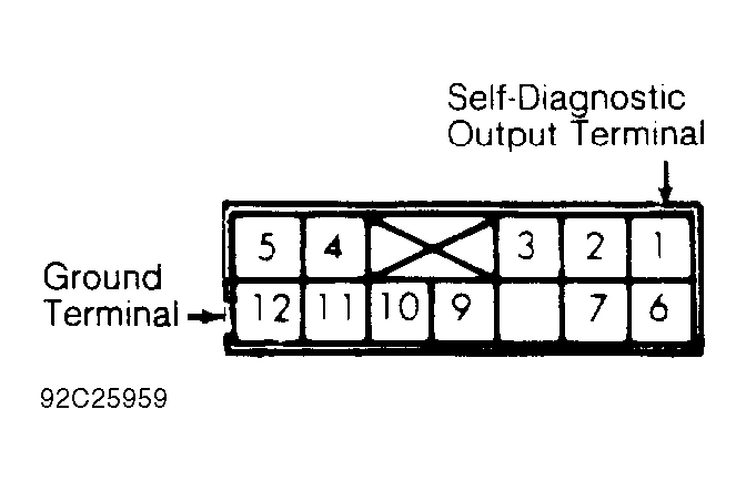
Fig. 1: Dodge Stealth R/T 1993 - Component Locations - Data Link Connector Terminal ID
Dodge Stealth R/T 1993 - DIAGNOSTIC TROUBLE CODE DEFINITIONS
NOTE: Codes listed in DIAGNOSTIC TROUBLE CODE INDEX table are not used on all vehicles.
NOTE: If MIL stays on, ECM may be faulty.
Dodge Stealth R/T 1993 DIAGNOSTIC TROUBLE CODE INDEX
Code (1) Description Possible Cause 11 Oxygen Sensor (O2S) (1-Wire Oxygen Sensor) Faulty O2S, Connector Or Harness, Low Or High Fuel Pressure, Defective Injector(s), Intake Air Leaks 11 Oxygen Sensor (O2S) (2-Wire Oxygen Sensor) Faulty O2S, Connector Or Harness, Low Or High Fuel Pressure, Defective Injector(s), Intake Air Leaks 11 Oxygen Sensor (O2S) (4-Wire Oxygen Sensor) Faulty O2S, Connector Or Harness, Low Or High Fuel Pressure, Defective Injector(s), Intake Air Leaks 12 Airflow Sensor Faulty Airflow Sensor, Connector Or Harness 13 Intake Air Temperature Sensor Faulty IAT Sensor, Connector Or Harness 14 Throttle Position Sensor Faulty TP Sensor, Connector Or Harness, Closed Throttle Position Switch 15 Idle Speed Control Position Sensor Faulty ISC Motor Position Sensor, Faulty Throttle Position Sensor, Connector Or Harness 21 Engine Coolant Temperature (ECT) Sensor Faulty ECT Sensor, Connector Or Harness 22 Crankshaft Position (CKP) Sensor Faulty Distributor Assembly (If Equipped), Faulty CKP Sensor, Connector Or Harness 23 Camshaft Position Sensor Faulty Distributor Assembly (If Equipped), Faulty CMP Sensor, Connector Or Harness 24 Vehicle Speed Sensor Faulty VSS, Connector Or Harness 25 Barometric Pressure Sensor Faulty BARO Pressure Sensor, Connector Or Harness 31 Knock Sensor Faulty Knock Sensor, Connector Or Harness 32 MAP Sensor Faulty MAP Sensor, Connector Or Harness 36 Ignition Timing Adjustment Signal Connector Or Harness 39 Oxygen Sensor (O2S) Faulty O2S Sensor, Faulty O2S Sensor Heater, Connector Or Harness, Low Or High Fuel Pressure, Defective Injector(s), Intake Air Leaks 41 Fuel Injector Low Or High Injector Coil Resistance, Connector Or Harness 42 Fuel Pump Faulty PCM, Faulty MFI Relay, Connector Or Harness 43 EGR Temperature Sensor Faulty EGR Valve, Faulty EGR Temperature Sensor, Faulty EGR Solenoid, Faulty EGR Vacuum Control, Connector Or Harness 44 Ignition Coils Faulty Ignition Coil, Faulty Ignition Power Transistor Unit, Connector Or Harness 52 Ignition Coils Faulty Ignition Coil, Faulty Ignition Power Transistor Unit, Connector Or Harness 53 Ignition Coils Faulty Ignition Coil, Faulty Ignition Power Transistor Unit, Connector Or Harness 55 Idle Air Control Position Sensor Faulty IAC Valve Position Sensor, Faulty IAC Motor Assembly, Faulty PCM, Connector Or Harness 59 Rear Oxygen Sensor (O2S) Faulty O2S Sensor, Faulty O2S Sensor Heater, Faulty PCM, Connector Or Harness 61 Transaxle Control Module Signal Faulty TCM, Connector Or Harness 62 Induction Control Valve Position Sensor Faulty VIC Valve Position Sensor, Connector Or Harness 71 Traction Control Vacuum Solenoid Faulty TC Vacuum Valve Solenoid, Connector Or Harness 72 Traction Control Vent Solenoid Faulty TC Vent Valve Solenoid, Connector Or Harness
(1) Perform appropriate test under DIAGNOSTIC TESTS.
Dodge Stealth R/T 1993 - CLEARING CODES
NOTE: To clear codes using a scan tester, refer to owners manual supplied with scan tester.
Fault codes may be cleared by disconnecting negative battery cable for at least 10 seconds, allowing ECM to clear fault codes. Reconnect negative battery cable and check for codes to confirm repair.
Dodge Stealth R/T 1993 - ECM LOCATION
Dodge Stealth R/T 1993 ECM LOCATION
Application Location Stealth & 3000GT Behind Radio Console Diamante Behind Right Side Of Instrument Panel
Dodge Stealth R/T 1993 - TERMINAL IDENTIFICATION
NOTE: The following terminals are shown as viewed from component side.
Dodge Stealth R/T 1993 TERMINAL ID DIRECTORY
Connector See
Fig.re Airflow Sensor Fig. 2 CKP/CMP Sensor Fig. 3 & Fig. 4 Coolant Temperature Sensor Fig. 5 ECM Fig. 6 EGR Temperature Sensor Fig. 7 Fuel Injector Fig. 8 , Fig. 9 , Fig. 10 & Fig. 11 Idle Air Control Valve Position Sensor Fig. 12 Idle Speed Control Motor & Position Sensor Fig. 13 Ignition Coil Fig. 14 Induction Control Valve Position Sensor Fig. 15 Knock Sensor Fig. 16 MAP Sensor Fig. 17 MPI Relay Fig. 18 Oxygen (O2) Sensor Fig. 19 , Fig. 20 & Fig. 21 Throttle Position Sensor Fig. 22 Traction Control Vacuum Solenoid Fig. 23 Traction Control Vent Solenoid Fig. 24 Transaxle Control Module Fig. 25
Fig. 2: Dodge Stealth R/T 1993 - Component Locations - Airflow Sensor Terminal ID

Fig. 3: Dodge Stealth R/T 1993 - Component Locations - CKP/CMP Sensor Terminal ID (SOHC)

Fig. 4: Dodge Stealth R/T 1993 - Component Locations - CKP/CMP Sensor Terminal ID (DOHC)


Fig. 6: Dodge Stealth R/T 1993 - Component Locations - ECM Terminal ID

Fig. 7: Dodge Stealth R/T 1993 - Component Locations - EGR Temperature Sensor Terminal ID


Fig. 11: Dodge Stealth R/T 1993 - Component Locations - Fuel Injector Terminal ID (All Other Models)


Fig. 14: Dodge Stealth R/T 1993 - Component Locations - Ignition Coil Terminal ID


Fig. 16: Dodge Stealth R/T 1993 - Component Locations - Knock Sensor Terminal ID

Fig. 17: Dodge Stealth R/T 1993 - Component Locations - Map Sensor Terminal ID

Fig. 18: Dodge Stealth R/T 1993 - Component Locations - MPI Relay Terminal ID


Fig. 20: Dodge Stealth R/T 1993 - Component Locations - Oxygen (O2) Sensor Terminal ID (Non-Turbo)

Fig. 21: Dodge Stealth R/T 1993 - Component Locations - Oxygen (O2) Sensor Terminal ID (4-Wire)

Fig. 22: Dodge Stealth R/T 1993 - Component Locations - Throttle Position Sensor Terminal ID

Fig. 23: Dodge Stealth R/T 1993 - Component Locations - Traction Control Vacuum Solenoid Terminal ID

Fig. 24: Dodge Stealth R/T 1993 - Component Locations - Traction Control Vent Solenoid Terminal ID

Fig. 25: Dodge Stealth R/T 1993 - Component Locations - Transaxle Control Module Terminal ID

Dodge Stealth R/T 1993 - DIAGNOSTIC TESTS
CAUTION: Ensure ignition switch is in OFF position when performing resistance tests.
NOTE: Perform all resistance and voltage tests using a Digital Volt-Ohmmeter (DVOM) with a minimum 10-megohms impedance, unless stated otherwise in test procedures.
Clear fault codes after each repair. See CLEARING CODES under SELF-DIAGNOSTIC SYSTEM. Recheck for codes to confirm repair. See RETRIEVING CODES under SELF-DIAGNOSTIC SYSTEM.
Dodge Stealth R/T 1993 - CODE 11: OXYGEN (O2) SENSOR, 1-WIRE O2 SENSOR
NOTE: For component terminal identification, see TERMINAL IDENTIFICATION . For wiring diagrams, see WIRING DIAGRAMS article.
- If using scan tester, go to step 2. Start and warm engine to operating temperature. Disconnect O2 sensor connector. Connect DVOM between chassis ground and O2 sensor terminal. While repeatedly racing engine, measure O2 sensor output voltage. If voltage is not .6-1.0 volt, replace O2 sensor. If voltage is within specification, go to step 4.
- Using scan tester, read O2 sensor voltage. While monitoring scan tester, accelerate to 4000 RPM. Suddenly decelerate. Scan tester should read .3 volt or less. Suddenly accelerate. Scan tester should read .5-1.0 volt. If voltage is not as specified, replace O2 sensor. If voltage is as specified, go to next step.
- While monitoring scan tester, accelerate to 2000 RPM and decelerate to 700 RPM (idle). Scan tester should switch between .6-1.0 volt and .4 volt or less. If voltage is not as specified, replace O2 sensor. If voltage is as specified, go to next step.
- Disconnect O2 sensor connector and ECM connector. Using DVOM, check for continuity between O2 sensor terminal and ECM connector terminal No. 4. If continuity does not exist, repair wiring harness as necessary. If continuity exists, condition required to set fault is not present at this time. Test is complete. Intermittent problem may exist. See TESTS W/O CODES article.
Dodge Stealth R/T 1993 - CODE 11: OXYGEN (O2) SENSOR, 2-WIRE O2 SENSOR
NOTE: For component terminal identification, see TERMINAL IDENTIFICATION . For wiring diagrams, see WIRING DIAGRAMS article.
- If using scan tester, go to step 2. Start and warm engine to operating temperature. Disconnect O2 sensor connector. Connect DVOM between chassis ground and O2 sensor terminal No. 1. While repeatedly racing engine, measure O2 sensor output voltage. If voltage is not .6-1.0 volt, replace O2 sensor. If voltage is within specification, go to step 4.
- Using scan tester, read O2 sensor voltage. While monitoring scan tester, accelerate to 4000 RPM. Suddenly decelerate. Scan tester should read .3 volt or less. Suddenly accelerate. Scan tester should read .5-1.0 volt. If voltage is not as specified, replace O2 sensor. If voltage is as specified, go to next step.
- While monitoring scan tester, accelerate to 2000 RPM and decelerate to 700 RPM (idle). Scan tester should switch between .6-1.0 volt and .4 volt or less. If voltage is not as specified, replace O2 sensor. If voltage is as specified, go to next step.
- Disconnect O2 sensor connector and ECM connector. Using DVOM, check for continuity between O2 sensor terminal No. 1 and ECM connector terminal No. 4. If continuity does not exist, repair wiring harness as necessary. If continuity exists, go to next step.
- Using DVOM, check continuity between chassis ground and O2 sensor connector terminal No. 2. If continuity does not exist, replace O2 sensor. If continuity exists, condition required to set fault is not present at this time. Test is complete. Intermittent problem may exist. See TESTS W/O CODES article.
Dodge Stealth R/T 1993 - CODE 11: OXYGEN (O2) SENSOR, 4-WIRE O2 SENSOR
NOTE: For component terminal identification, see TERMINAL IDENTIFICATION . For wiring diagrams, see WIRING DIAGRAMS article.
- If using scan tester, go to step 3. Disconnect O2 sensor connector. On all models except Diamante, Stealth non-turbo and 3000GT non-turbo, install Test Harness (MB998464 ) between O2 sensor and O2 sensor connector. On all models, use DVOM to check resistance between specified O2 sensor connector heater terminals. See O2 SENSOR 4-WIRE CONNECTOR TERMINAL ID table. O2 sensor resistance should be 20 ohms at 68?F (20?C). If resistance is not as specified, replace O2 sensor. If resistance is as specified, go to next step.
- Using jumper wires, apply 12 volts to specified O2 sensor connector heater terminals. See O2 SENSOR 4-WIRE CONNECTOR TERMINAL ID table. Using DVOM, check voltage between specified O2 sensor connector output terminals, while repeatedly racing engine. If voltage is not .6-1.0 volt, replace O2 sensor. If voltage is .6-1.0 volt, go to step 5.
Dodge Stealth R/T 1993 O2 SENSOR 4-WIRE CONNECTOR TERMINAL ID
Application (1) Heater Terminals Output Terminals Turbo 1 & 3 2 & 4 Non-Turbo 3 & 4 1 & 2 (1) First terminal listed is positive. Second terminal listed is negative. - Start and warm engine to operating temperature. Using scan tester, read O2 sensor voltage. While monitoring scan tester, accelerate to 4000 RPM. Suddenly decelerate. Scan tester should read .3 volt or less. Suddenly accelerate. Scan tester should read .5-1.0 volt. If voltage is not as specified, replace O2 sensor. If voltage is as specified, go to next step.
- While monitoring scan tester, accelerate to 2000 RPM and decelerate to 700 RPM (idle). Scan tester should switch between .6-1.0 volt and .4 volt or less. If voltage is not as specified, replace O2 sensor. If voltage is as specified, go to next step.
- Disconnect O2 sensor connector. On Stealth and 3000GT, go to next step. On all other models, disconnect MPI relay connector. Using DVOM, check for continuity between specified O2 sensor connector terminals and MPI connector terminals. See O2 SENSOR TO MPI WIRING HARNESS TERMINAL ID table. If continuity does not exist, repair wiring harness as necessary. If continuity exists, go to step 7.
Dodge Stealth R/T 1993 O2 SENSOR TO MPI WIRING HARNESS TERMINAL ID
Application O2 Sensor Terminals MPI Terminals Diamante 3 5 All Other Models 2 2 - Turn ignition switch to ON position. Using DVOM, check voltage between specified O2 sensor connector terminal and chassis ground. See O2 SENSOR CONNECTOR VOLTAGE CIRCUIT ID table. If system voltage does not exist, repair wiring harness as necessary. If system voltage exists, go to next step.
Dodge Stealth R/T 1993 O2 SENSOR CONNECTOR VOLTAGE CIRCUIT ID
Application Terminal No. Stealth & 3000GT (Non-Turbo) 3 Stealth & 3000GT (Turbo) 1 - Using DVOM, check for continuity between specified O2 sensor connector terminals and ECM connector terminals. See O2 SENSOR TO ECM WIRING HARNESS TERMINAL ID table. If continuity does not exist on either circuit, repair appropriate circuit for open or short to ground as necessary. If continuity exists, go to next step.
Dodge Stealth R/T 1993 O2 SENSOR TO ECM WIRING HARNESS TERMINAL ID
Application O2 Sensor Terminals ECM Terminals Diamante 1 56 Stealth Non-Turbo & 3000GT Non-Turbo 1 56 Stealth Turbo & 3000GT Turbo 4 56 - Disconnect O2 sensor connector. Using DVOM, check for continuity between specified O2 sensor connector terminal and chassis ground. See O2 SENSOR CONNECTOR GROUND CIRCUIT ID table. If continuity does not exist, repair wiring harness as necessary. If no system or component malfunctions occur in preceding tests, condition required to set fault is not present at this time. Test is complete. Intermittent problem may exist. See TESTS W/O CODES article.
Dodge Stealth R/T 1993 O2 SENSOR CONNECTOR GROUND CIRCUIT ID
Application Terminal No. All Models 2
Dodge Stealth R/T 1993 - CODE 12: AIRFLOW SENSOR
NOTE: For component terminal identification, see TERMINAL IDENTIFICATION . For wiring diagrams, see WIRING DIAGRAMS article.
NOTE: Procedures are provided by manufacturer for component testing using an engine analyzer with oscilloscope capability. - manufacturer's operation manual for instructions in use of oscilloscope. If using a scan tester, go to step 3.
- If using scan tester, go to step 3. Disconnect Airflow Sensor (AFS) connector. Install Test Harness (MB991348 ) between AFS and AFS connector. Using engine analyzer with oscilloscope capability, connect special patterns probe to AFS connector terminal No. 3.
- Start engine. Verify that wave form high frequency and low frequency patterns are of approximately the same length (time). See Fig. 26 . Verify that wave length decreases and frequency increases as engine RPM increases. If conditions are not as specified, replace AFS. If conditions are as specified, go to step 4.
Fig. 26: Dodge Stealth R/T 1993 - Component Locations - Known-Good Airflow Sensor Wave Pattern ID - Warm vehicle to normal operating temperature. Ensure headlights and accessories are off. Ensure steering wheel is in straight-ahead position. Using scan tester, read Airflow Sensor (AFS) volume (frequency) value. See AIRFLOW SENSOR VALUES table. Frequency should increase when engine is raced. If values are not as specified, replace AFS. If values are as specified, go to next step.
Dodge Stealth R/T 1993 AIRFLOW SENSOR VALUES
Type Hz @ 700 RPM Hz @ 2000 RPM Diamante & Stealth SOHC 21-47 57-97 Stealth & 3000GT DOHC Non-Turbo 22-48 50-90 DOHC Turbo 22-48 68-108 - On Stealth and 3000GT, go to step 8. On all other models, disconnect AFS connector and MPI relay connector. Using DVOM, check for continuity between specified AFS connector terminal and MPI relay connector terminal. See AFS TO MPI TERMINAL WIRING HARNESS ID table. If continuity does not exist, repair wiring harness as necessary. If continuity exists, go to next step.
Dodge Stealth R/T 1993 AFS TO MPI TERMINAL WIRING HARNESS ID
Application AFS Terminal No. MPI Terminal No. All Models 4 3 - Using DVOM, check for continuity between chassis ground and AFS connector terminal No. 5. If continuity does not exist, repair wiring harness as necessary. If continuity exists, go to next step.
- Disconnect AFS connector and ECM connector. Using DVOM, check for continuity between specified AFS connector terminal and ECM connector terminal. See AFS TO ECM WIRING HARNESS TERMINAL ID table. If continuity does not exist on specified circuit(s), repair appropriate circuit for open or short to ground as necessary. If continuity exists, go to next step.
Dodge Stealth R/T 1993 AFS TO ECM WIRING HARNESS TERMINAL ID
Application AFS Terminal No. ECM Terminal No. All Models 3 70 All Models 7 19 - Turn ignition switch to ON position. Using DVOM, check voltage between chassis ground and AFS harness connector terminal No. 3 on all models. If voltage is not 4.8-5.2 volts, replace ECM. If voltage is as specified, condition required to set fault is not present at this time. Test is complete. Intermittent problem may exist. See TESTS W/O CODES article.
- Disconnect AFS connector. Turn ignition switch to ON position. Using DVOM, check voltage between specified terminal and chassis ground. See AFS CONNECTOR POWER SUPPLY CIRCUIT ID table. If system voltage does not exist, repair wiring harness as necessary. If system voltage exists, go to next step.
Dodge Stealth R/T 1993 AFS CONNECTOR POWER SUPPLY CIRCUIT ID
Application Terminal No. Stealth & 3000GT 4 - With ignition switch in ON position, use DVOM to check voltage between specified terminal and chassis ground. See AFS CONNECTOR VOLTAGE CIRCUIT ID table. If voltage is not 4.8-5.2 volts, repair wiring harness as necessary. If voltage is as specified, go to next step.
Dodge Stealth R/T 1993 AFS CONNECTOR VOLTAGE CIRCUIT ID
Application Terminal No. All Models 3 - Using DVOM, check for continuity between specified AFS connector terminal and chassis ground. See AFS CONNECTOR GROUND CIRCUIT ID table. If continuity does not exist, repair wiring harness as necessary. Go to next step.
Dodge Stealth R/T 1993 AFS CONNECTOR GROUND CIRCUIT ID
Application Terminal No. All Models 5 - Disconnect AFS connector and ECM connector. Using DVOM, check for continuity between specified AFS connector terminal and ECM connector terminal. See ECM TO AFS WIRING HARNESS TERMINAL table. If continuity does not exist on specified circuit(s), repair appropriate circuit for open or short to ground as necessary. If continuity exists, condition required to set fault is not present at this time. Test is complete. Intermittent problem may exist. See TESTS W/O CODES article.
Dodge Stealth R/T 1993 ECM TO AFS WIRING HARNESS TERMINAL
Application ECM Terminal No. AFS Terminal No. Stealth & 3000GT 19 7 Diamante 57 7

Dodge Stealth R/T 1993 - CODE 13: INTAKE AIR TEMPERATURE SENSOR
NOTE: On all models, intake air temperature sensor is built into airflow sensor. For code 13 test purposes, the airflow sensor will be referred to as the intake air temperature sensor. For component terminal identification, see AIRFLOW SENSOR under TERMINAL IDENTIFICATION . For wiring diagrams, see WIRING DIAGRAMS article.
- If using scan tester, go to step 3. Disconnect Intake Air Temperature (IAT) sensor connector. Using a thermometer, check engine compartment ambient temperature. Using DVOM, check resistance between specified IAT sensor terminals. See IAT SENSOR TERMINAL ID table. Resistance should be 6000 ohms at 32?F (0?C), 2700 ohms at 68?F (20?C) or 400 ohms at 176?F (80?C). If resistance is not as specified, replace IAT sensor. If resistance is as specified, go to next step.
Dodge Stealth R/T 1993 IAT SENSOR TERMINAL IDENTIFICATION
Application Terminals No. All Models 5 & 6
Fig. 27: Dodge Stealth R/T 1993 - Component Locations - IAT Component Terminals (1.5L) ID - Using a hair dryer, warm IAT sensor while monitoring DVOM. Resistance should decrease evenly as temperature rises. If resistance remains unchanged, replace IAT sensor. If resistance changes, go to step 4.
- Turn ignition switch to ON or RUN position. Using a thermometer, check engine compartment ambient temperature. Using scan tester, read Intake Air Temperature (IAT) sensor temperature. See IAT SENSOR TEMPERATURE table. If temperatures are not as specified, replace IAT sensor. If temperatures are as specified, go to next step.
Dodge Stealth R/T 1993 IAT SENSOR TEMPERATURE
Ambient Temperature Standard Value -4?F (-20?C) -20?C 32?F (0?C) 0?C 68?F (20?C) 20?C 104?F (40?C 40?C 176?F (80?C) 80?C - Disconnect IAT sensor connector. Using DVOM, check for continuity between chassis ground and specified IAT sensor connector terminal. See IAT SENSOR GROUND CIRCUIT TERMINAL ID table. If continuity does not exist, repair wiring harness as necessary. If continuity exists, go to next step.
Dodge Stealth R/T 1993 IAT SENSOR GROUND CIRCUIT TERMINAL ID
Application Terminal No. All Models 5 - On Stealth and 3000GT, go to next step. On all other models, with IAT sensor connector and ECM connector disconnected, check for continuity between specified IAT sensor connector terminal and ECM connector terminal. See IAT TO ECM WIRING HARNESS TERMINAL ID table. If continuity does not exist, repair wiring harness as necessary. If continuity exists, go to next step.
Dodge Stealth R/T 1993 IAT TO ECM WIRING HARNESS TERMINAL ID
Application IAT Connector Terminal No. ECM Connector Terminal No. All Models 6 52 - Turn ignition switch to ON position. Check voltage between chassis ground and specified IAT sensor connector. See IAT SENSOR CONNECTOR VOLTAGE SUPPLY CIRCUIT TERMINAL ID table. If voltage is not 4.5-4.9 volts, replace ECM. If voltage is as specified, replace IAT sensor.
Dodge Stealth R/T 1993 IAT SENSOR CONNECTOR VOLTAGE SUPPLY CIRCUIT TERMINAL ID
Application Terminal No. All Models 6

Dodge Stealth R/T 1993 - CODE 14: THROTTLE POSITION SENSOR
NOTE: For component terminal identification, see TERMINAL IDENTIFICATION . For wiring diagrams, see WIRING DIAGRAMS article.
- If using scan tester, go to step 3. Disconnect Throttle Position Sensor (TPS) connector. Using DVOM, check resistance between TPS terminals No. 1 and 4. If resistance is not 3500-6500 ohms, replace TPS. If resistance is as specified, go to next step
- Check resistance between specified TPS terminals. See TPS TERMINAL ID table. While monitoring DVOM, slowly open throttle from idle to fully open position. If resistance does not change smoothly, replace TPS. If resistance changes smoothly, go to step 4.
Dodge Stealth R/T 1993 TPS TERMINAL ID
Application Terminals No. All Models 2 & 4 - Turn ignition switch to ON position. Using scan tester, read Throttle Position Sensor (TPS) voltage. With throttle at idle, voltage should read .3-1.0 volt. Voltage should increase while slowly opening throttle. At wide open throttle, voltage should read 4.5-5.5 volts. If voltage is not as specified, replace TPS. If voltage is as specified, go to next step.
- On Stealth and 3000GT, go to step 7. On all other models, disconnect TPS connector. Using DVOM, check continuity between chassis ground and specified TPS connector terminal. See TPS CONNECTOR GROUND CIRCUIT ID table. If continuity does not exist, repair wiring harness as necessary. If continuity exists, go to next step.
Dodge Stealth R/T 1993 TPS CONNECTOR GROUND CIRCUIT ID
Application Terminal No. All Models 4 - Disconnect TPS connector and ECM connector. Check for continuity between specified TPS connector terminal and ECM connector terminal. See TPS TO ECM WIRING HARNESS TERMINAL ID table. If continuity does not exist, repair wiring harness as necessary. If continuity exists, go to next step.
Dodge Stealth R/T 1993 TPS TO ECM WIRING HARNESS TERMINAL ID
Application TPS Terminal No. ECM Terminal No. Diamante 1 61 2 64 - Check voltage between chassis ground and specified TPS connector terminal. See TPS VOLTAGE CIRCUIT ID table. If voltage is not 4.8-5.2 volts, replace ECM. If voltage is as specified, condition required to set fault is not present at this time. Test is complete. Intermittent problem may exist. TESTS W/O CODES article.
Dodge Stealth R/T 1993 TPS VOLTAGE CIRCUIT ID
Application TPS Terminal No. Diamante 1 - Disconnect TPS connector. Turn ignition switch to ON position. Using DVOM, check voltage between chassis ground and specified TPS connector terminal. See TPS VOLTAGE SUPPLY ID table. If voltage is not 4.8-5.2 volts, repair wiring harness as necessary. If voltage is as specified, go to next step.
Dodge Stealth R/T 1993 TPS VOLTAGE SUPPLY ID
Application TPS Terminal No. Stealth & 3000GT 4 - Check continuity between chassis ground and specified TPS connector terminal. See TPS CONNECTOR GROUND CIRCUIT ID table. If continuity does not exist, repair wiring harness as necessary. If continuity exists, go to next step.
Dodge Stealth R/T 1993 TPS CONNECTOR GROUND CIRCUIT ID
Application Terminal No. All Models 4 - With TPS connector and ECM connector disconnected, check for continuity between specified TPS connector terminal and ECM connector terminal. See ECM TO TPS HARNESS ID table. If continuity does not exist, repair wiring harness as necessary. If continuity exists, condition required to set fault is not present at this time. Test is complete. Intermittent problem may exist. See TESTS W/O CODES article.
Dodge Stealth R/T 1993 ECM TO TPS HARNESS ID
Application ECM Terminal No. TPS Terminal No. Stealth & 3000GT 64 2 Diamante 9 2
Dodge Stealth R/T 1993 - CODE 15: IDLE SPEED CONTROL POSITION SENSOR
NOTE: For component terminal identification, see TERMINAL IDENTIFICATION . For wiring diagrams, see WIRING DIAGRAMS article.
- If using scan tester, go to step 3. Disconnect Idle Speed Control (ISC) motor position sensor connector. Using DVOM, check resistance between ISC motor position sensor terminals No. 2 and 3. If resistance is not 4000-6000 ohms, replace ISC motor position sensor. If resistance is as specified, go to next step.
CAUTION: Apply only 6 volts DC or less to ISC motor connector. Higher voltage could cause servo gears to lock up. - Disconnect ISC motor connector. Connect a 6-volt DC power supply between ISC motor connector terminals No. 1 and 2 to operate ISC motor. Check resistance between ISC motor position sensor terminals No. 3 and 5. Ensure ISC motor position sensor resistance changes smoothly as motor extends and retracts. If resistance does not change smoothly, replace ISC motor assembly. If resistance changes smoothly, go to step 4.
- Ensure engine coolant temperature is 185-205?F (85-95?C). Place transmission in Park or Neutral. Turn off all accessories except A/C. Ensure A/C clutch is operating when A/C system is on. With engine at idle, use scan tester to read Idle Speed Control (ISC) motor position sensor voltage. See ISC VOLTAGE SPECIFICATIONS table. If voltage is not as specified, replace IAC motor position sensor. If voltage is as specified, go to next step.
Dodge Stealth R/T 1993 ISC VOLTAGE SPECIFICATIONS
Application A/C Switch Position Standard Voltage All Models Off .5-1.3 On .9-2.3 (1) .9-2.3 (1) On A/T models only, apply brakes, place transmission selector in "D" position and A/C switch in ON position. - Disconnect ISC motor position sensor connector. Turn ignition switch to ON position. Using DVOM, check voltage between chassis ground and sensor connector terminal No. 2. Check voltage between chassis ground and sensor connector terminal No. 6. Voltage should be 4.8-5.2 volts on both circuits. If voltage is not as specified, repair appropriate wiring harness circuit(s) as necessary. If voltage is as specified, go to next step.
- Check for continuity between chassis ground and sensor connector terminal No. 3. If continuity does not exist, repair wiring harness as necessary. If continuity exists, condition required to set fault is not present at this time. Test is complete. Intermittent problem may exist. See TESTS W/O CODES article.
Dodge Stealth R/T 1993 - CODE 21: COOLANT TEMPERATURE SENSOR
NOTE: For component terminal identification, see TERMINAL IDENTIFICATION . For wiring diagrams, see WIRING DIAGRAMS article.
- If using scan tester, go to step 2. Remove Coolant Temperature Sensor (CTS) from intake manifold. Submerge temperature sensing portion of CTS in hot water. Using DVOM, check resistance across CTS terminals. See CTS RESISTANCE SPECIFICATIONS table. If resistance is not as specified, replace CTS. If resistance is as specified, go to step 3.
Dodge Stealth R/T 1993 CTS RESISTANCE SPECIFICATIONS
Water Temperature Approximate Ohms 32?F (0?C) 5800 68?F (20?C) 2400 104?F (40?C) 1100 176?F (80?C) 300 - Turn ignition switch to ON or RUN position. Using a thermometer, check engine compartment ambient temperature. Using scan tester, read Coolant Temperature Sensor (CTS) voltage. See CTS VOLTAGE SPECIFICATIONS table. If voltage is not within specifications, replace CTS. If voltage is within specification, go to next step.
Dodge Stealth R/T 1993 CTS VOLTAGE SPECIFICATIONS
Ambient Temperature Standard Value ?F (?C) -4?F (-20?C) -20?C 32?F (0?C) 0?C 68?F (20?C) 20?C 104?F (40?C 40?C 176?F (80?C) 80?C - Disconnect CTS connector. Using DVOM, check continuity between chassis ground and specified connector terminal. See CTS GROUND CIRCUIT TERMINAL ID table. If continuity does not exist, repair wiring harness as necessary. If continuity exists, go to next step.
Dodge Stealth R/T 1993 CTS GROUND CIRCUIT TERMINAL ID
Application Terminal No. All Models 2 - On Stealth, and 3000GT, go to next step. On all other models, Disconnect CTS connector and ECM connector. Check continuity between specified CTS connector terminals and ECM connector terminals. See CTS TO ECM WIRING HARNESS TERMINAL ID table. If continuity does not exist, repair wiring harness as necessary. If continuity exists, go to next step.
Dodge Stealth R/T 1993 CTS TO ECM WIRING HARNESS TERMINAL ID
Application CTS Terminal No. ECM Terminal No. All Models 1 63 - Turn ignition switch to ON position. Check voltage between chassis ground and specified CTS connector terminal. See CTS VOLTAGE CIRCUIT ID table. If voltage is not 4.5-4.9 volts, replace ECM. If voltage is as specified, condition required to set fault is not present at this time. Test is complete. Intermittent problem may exist. See TESTS W/O CODES article.
Dodge Stealth R/T 1993 CTS VOLTAGE CIRCUIT ID
Application Terminal No. All Models 2
Dodge Stealth R/T 1993 - CODE 22: CRANKSHAFT POSITION SENSOR
NOTE: For component terminal identification, see TERMINAL IDENTIFICATION . For wiring diagrams, see WIRING DIAGRAMS article.
NOTE: Procedures are provided by manufacturer for component testing using an engine analyzer with oscilloscope capability. - manufacturer's operation manual for instructions in use of oscilloscope. If using a scan tester, go to step 3.
- On Diamante, disconnect Crankshaft/Camshaft Position (CKP/CMP) sensor connector. Install Test Harness (MB991348) between sensor and connector. On all models, using engine analyzer with oscilloscope capability, connect special patterns probe to specified connector terminal. See CKP PATTERN PICKUP TERMINAL ID table.
Dodge Stealth R/T 1993 CKP PATTERN PICKUP TERMINAL ID
Application Terminal No. All Models 2 - Start engine. Compare oscilloscope wave pattern with known-good wave pattern. See Fig. 28 . Verify that wave length (time) decreases as engine RPM increases. If a wave pattern is output and it fluctuates to left or right, check for loose timing belt or an abnormality in sensor pickup disc. If a rectangular wave pattern is output even when engine is not started, substitute known-good CKP sensor. Repeat test. If wave pattern is still abnormal, go to step 5.
Fig. 28: Dodge Stealth R/T 1993 - Component Locations - Known-Good CKP Sensor Wave Pattern ID - Connect an engine tachometer. Crank engine. Ensure ignition coil primary current toggles on and off. Using tachometer and scan tester, compare cranking speed and scan tester read out. If engine fails to start and tachometer reads zero RPM when engine is cranked, check for broken timing belt or faulty CKP sensor. If CKP sensor is suspected, substitute known-good CKP sensor. Repeat test procedure. If engine fails to start, tachometer reads zero RPM, and ignition coil primary current fails to toggle on and off, check for faulty ignition coil, ignition circuit or power transistor. If engine starts and readouts agree, go to next step.
- Ensure A/C switch is in ON position to activate closed throttle position switch. Allow engine to idle. Check coolant temperature. Using scan tester, read idle speed. See IDLE RPM SPECIFICATIONS table. If RPM is not to specification, check for faulty coolant temperature sensor, basic idle speed adjustment, or idle air control motor. If RPM is within specifications, go to next step.
Dodge Stealth R/T 1993 IDLE RPM SPECIFICATIONS
Coolant Temperature Engine RPM -4?F (-20?C): All Models 1300-1500 32?F (0?C): All Models 1250-1450 68?F (20?C) Diamante DOHC, Stealth DOHC & 3000GT 1100-1300 Diamante SOHC, Stealth SOHC 1050-1250 104?F (40?C) Diamante DOHC, Stealth DOHC & 3000GT 950-1150 Diamante SOHC, Stealth SOHC 850-1050 176?F (80?C): All Models 600-800 - Disconnect CKP/CMP sensor connector and Ignition (IG) switch connector. Using DVOM, check for continuity between CKP/CMP sensor connector terminal No. 2 and IG switch connector terminal No. 3. See Fig. 29 . If continuity does not exist, repair wiring harness as necessary. If continuity exists, go to step 8.
Fig. 29: Dodge Stealth R/T 1993 - Component Locations - Ignition Switch Terminal ID - On all other models except Diamante, go to next step. Disconnect CKP/CMP connector and MPI relay connector. Using DVOM, check for continuity between CKP/CMP connector terminal No. 3 and MPI relay connector terminal No. 5. If continuity does not exist, repair wiring harness as necessary. If continuity exists, go to step 8.
- On all other models, disconnect CKP/CMP sensor connector. Turn ignition switch to ON position. Using DVOM, check voltage between chassis ground and specified CKP/CMP sensor connector terminal. See CKP SENSOR VOLTAGE TERMINAL ID table. If battery voltage does not exist, repair ignition circuit between CKP/CMP sensor connector and Ignition switch. If battery voltage exists, go to next step.
Dodge Stealth R/T 1993 CKP SENSOR VOLTAGE TERMINAL ID
Application Terminal No. All Models 3 - With CKP/CMP sensor connector disconnected, check for continuity between chassis ground and specified CKP/CMP sensor connector terminal. See CKP SENSOR GROUND CIRCUIT TERMINAL ID table. If continuity does not exist, repair wiring harness as necessary. If continuity exists, go to next step.
Dodge Stealth R/T 1993 CKP SENSOR GROUND CIRCUIT TERMINAL ID
Application Terminal No. Diamante SOHC & Stealth SOHC 4 All Other Models 1 - On Stealth and 3000GT, go to next step. On Diamante, with CKP/CMP sensor connector and ECM connector disconnected, check for continuity between specified CKP/CMP sensor connector terminal and ECM connector terminal. See CKP TO ECM CONNECTOR TERMINAL ID table. If continuity does not exist, repair wiring harness as necessary. If continuity exists, go to next step.
Dodge Stealth R/T 1993 CKP TO ECM CONNECTOR TERMINAL ID
Application CKP Terminal No. ECM Terminal No. Diamante 2 69 All Other Models 3 69 - With ignition switch in ON position, check for voltage between chassis ground and specified CKP/CMP sensor connector terminal. See CKP SENSOR SUPPLY CIRCUIT ID table. If 4.8-5.2 volts do not exist, replace ECM. If voltage is to specification and CKP sensor is suspected, replace CKP sensor.
Dodge Stealth R/T 1993 CKP SENSOR SUPPLY CIRCUIT ID
Application Terminal No. All Models 2


Dodge Stealth R/T 1993 - CODE 23: CAMSHAFT POSITION SENSOR
NOTE: For component terminal identification, see TERMINAL IDENTIFICATION . For wiring diagrams, see WIRING DIAGRAMS article.
NOTE: Procedures are provided by manufacturer for component testing using an engine analyzer with oscilloscope capability. - manufacturer's operation manual for instructions in use of oscilloscope. Manufacturer does not provide procedures for testing component using a scan tester.
- On all models except Stealth and 3000GT, disconnect Crankshaft/Camshaft Position (CKP/CMP) sensor connector. Install Test Harness (MB991348) between sensor and connector. On all models, using engine analyzer with oscilloscope capability, connect special patterns probe to specified connector terminal. See CMP PATTERN PICKUP TERMINAL ID table.
Dodge Stealth R/T 1993 CMP PATTERN PICKUP TERMINAL ID
Application Terminal No. Diamante SOHC, Stealth & 3000GT 1 Diamante DOHC 2 - Start engine. Compare oscilloscope wave pattern with known-good wave pattern. See Fig. 30 . Verify that wave length (time) decreases as engine RPM increases. If a wave pattern is output and it fluctuates to left or right, check for loose timing belt or an abnormality in sensor pickup disc. If a rectangular wave pattern is output even when engine is not started, substitute known-good CMP sensor. Repeat test. If wave pattern is still abnormal, go to next step.
Fig. 30: Dodge Stealth R/T 1993 - Component Locations - Known-Good CMP Sensor Wave Pattern ID - On all other models except Diamante, go to next step. Disconnect CKP/CMP connector and MPI relay connector. Using DVOM, check for continuity between CKP/CMP connector terminal No. 3 and MPI relay connector terminal No. 5. If continuity does not exist, repair wiring harness as necessary. If continuity exists, go to step 6.
- On all other models, disconnect CKP/CMP sensor connector. Turn ignition switch to ON position. Using DVOM, check voltage between chassis ground and specified CKP/CMP sensor connector terminal. See CMP SENSOR VOLTAGE TERMINAL ID table. If battery voltage does not exist, repair ignition circuit between CKP/CMP sensor connector and Ignition switch. If battery voltage exists, go to next step.
Dodge Stealth R/T 1993 CMP SENSOR VOLTAGE TERMINAL ID
Application Terminal No. All Models 3 - With CKP/CMP sensor connector disconnected, check for continuity between chassis ground and specified CKP/CMP sensor connector terminal. See CMP SENSOR GROUND CIRCUIT TERMINAL ID table. If continuity does not exist, repair wiring harness as necessary. If continuity exists, go to next step.
Dodge Stealth R/T 1993 CMP SENSOR GROUND CIRCUIT TERMINAL ID
Application Terminal No. Diamante SOHC & Stealth SOHC 4 All Other Models 1 - On Stealth and 3000GT, go to next step. On all other models, with CKP/CMP sensor connector and ECM connector disconnected, check for continuity between specified CKP/CMP sensor connector terminal and ECM connector terminal. See CMP TO ECM CONNECTOR TERMINAL ID table. If continuity does not exist, repair wiring harness as necessary. If continuity exists, go to next step.
Dodge Stealth R/T 1993 CMP TO ECM CONNECTOR TERMINAL ID
Application CMP Terminal No. ECM Terminal No. Diamante SOHC 1 68 DOHC 2 68 All Other Models 4 68 - With ignition switch in ON position, check for voltage between chassis ground and specified CKP/CMP sensor connector terminal. See CMP SENSOR SUPPLY CIRCUIT ID table. If 4.8-5.2 volts do not exist, replace ECM. If voltage is as specified, condition required to set fault is not present at this time. Test is complete. Intermittent problem may exist. See TESTS W/O CODES article.
Dodge Stealth R/T 1993 CMP SENSOR SUPPLY CIRCUIT ID
Application Terminal No. SOHC 1 DOHC 2

Dodge Stealth R/T 1993 - CODE 24: VEHICLE SPEED SENSOR
NOTE: For component terminal identification, see TERMINAL IDENTIFICATION . For wiring diagrams, see WIRING DIAGRAMS article.
- Manufacturer does not provide Vehicle Speed Sensor (VSS) testing procedures using scan tester. VSS is located in speedometer. VSS component testing procedures using DVOM require removal of instrument panel. Removal and installation of instrument panel is basically an unbolt and bolt-on procedure.
- On Stealth turbo and 3000GT turbo, go to next step. On all other models, use DVOM to check continuity between indicated VSS terminals. See Fig. 31 , Fig. 32 or Fig. 33 . Ensure continuity pulses on and off 4 times per speedometer shaft revolution. If continuity is not as specified, replace VSS. If continuity is as specified, go to step 4.
- Remove VSS. Connect battery, resistor (3-10 ohms) and voltmeter to indicated terminals. See Fig. 31 , Fig. 32 or Fig. 33 . Ensure voltage pulses 4 times per speedometer shaft revolution. If voltage is not as specified, replace VSS. If voltage is as specified, go to next step.
Fig. 31: Dodge Stealth R/T 1993 - Component Locations - VSS Test Terminal ID (Diamante) - Disconnect ECM connector. Using DVOM, check continuity between chassis ground and specified ECM connector terminal. See VSS OUTPUT CIRCUIT ID table. Move vehicle. Ensure continuity pulses on and off 4 times per tire revolution. If continuity is as specified: On Stealth and 3000GT, conditions required to set code are not present at this time, test is complete; on all other models, go to step 7. If continuity is not as specified: Stealth and 3000GT, go to step 6. On all other models, go to next step.
Dodge Stealth R/T 1993 VSS OUTPUT CIRCUIT ID
Application Terminal No. All Models 66 - With ECM connector disconnected, disconnect VSS connector. Ground ECM connector VSS output terminal. See VSS OUTPUT CIRCUIT ID table. Using DVOM, check for continuity between chassis ground and specified VSS connector terminal. See ECM TO VSS CIRCUIT ID table. If continuity does not exist, repair wiring harness as necessary. If continuity exists, go to next step.
Dodge Stealth R/T 1993 ECM TO VSS CIRCUIT ID
Application Terminal No. All Models 9 - With VSS connector disconnected, check for continuity between chassis ground and specified VSS connector terminal. See VSS GROUND CIRCUIT ID table. If continuity does not exist, repair wiring harness as necessary. If continuity exists, go to next step.
Dodge Stealth R/T 1993 VSS GROUND CIRCUIT ID
Application Terminal No. Diamante 13 Stealth & 3000GT 102 - With VSS connector and ECM connector disconnected, turn ignition switch to ON position. Using DVOM, check for voltage between chassis ground and specified VSS connector terminal. See VSS VOLTAGE FEED CIRCUIT ID table. If voltage is not 4.5-4.9 volts, replace ECM. If voltage is as specified, condition required to set fault is not present at this time. Test is complete. Intermittent problem may exist. See TESTS W/O CODES article.
Dodge Stealth R/T 1993 VSS VOLTAGE FEED CIRCUIT ID
Application Terminal No. Stealth & 3000GT 109 Diamante 9


Dodge Stealth R/T 1993 - CODE 25: BAROMETRIC PRESSURE SENSOR
NOTE: Barometric (BARO) pressure sensor is built into airflow sensor. For code 25 test purposes, the airflow sensor will be referred to as the BARO pressure sensor. For component terminal identification, see AIRFLOW SENSOR under TERMINAL IDENTIFICATION . For wiring diagrams, see WIRING DIAGRAMS article.
- Manufacturer does not provide component testing procedure without scan tester. Turn ignition switch to ON position. Using scan tester, read sensor pressure. See BARO PRESSURE SENSOR SPECIFICATIONS table. If pressure is not as specified, replace BARO pressure sensor. If pressure is as specified, go to next step.
Dodge Stealth R/T 1993 BARO PRESSURE SENSOR SPECIFICATIONS
Altitude: Ft. (M) Pressure: In. Hg 0 (0) 29.92 1969 (600) 27.95 3937 (1200) 25.98 5906 (1800) 24.02 - Disconnect BARO pressure sensor connector. Using DVOM, check for continuity between chassis ground and specified BARO pressure sensor connector terminal. See BARO PRESSURE SENSOR GROUND CIRCUIT ID table. If continuity does not exist, repair wiring harness as necessary. If continuity exists, go to next step.
Dodge Stealth R/T 1993 BARO PRESSURE SENSOR GROUND CIRCUIT ID
Application Terminal No. All Models 5 - On Stealth and 3000GT, go to step 5. On all other models, with BARO pressure sensor disconnected, disconnect ECM connector. Check for continuity between specified ECM connector terminal and BARO pressure sensor connector terminal. See BARO PRESSURE SENSOR TO ECM CIRCUIT ID table. If continuity does not exist, repair wiring harness as necessary. If continuity exists, go to next step.
Dodge Stealth R/T 1993 BARO PRESSURE SENSOR TO ECM CIRCUIT ID
Application BARO Terminal No. ECM Terminal No. Diamante 1 61 2 65 All Models 2 65 - With BARO pressure sensor connector and ECM connector disconnected, turn ignition switch to ON position. Check for voltage between chassis ground and BARO pressure sensor connector terminal No. 1. If voltage is not 4.8-5.2 volts, replace ECM. If voltage is as specified, condition required to set code is not present at this time. Test is complete. Intermittent problem may exist. See TESTS W/O CODES article.
- With BARO pressure sensor connector disconnected, turn ignition switch to ON position. Check for voltage between chassis ground and specified BARO pressure sensor connector terminal. See BARO PRESSURE SENSOR POWER SUPPLY CIRCUIT ID table. If voltage is not 4.8-5.2 volts, repair wiring harness as necessary. If voltage is as specified, go to next step.
Dodge Stealth R/T 1993 BARO PRESSURE SENSOR POWER SUPPLY CIRCUIT ID
Application Terminal No. All Models 1 - With BARO pressure sensor connector and ECM connector disconnected, ground ECM connector terminal No. 16 (terminal No. 65 on Stealth and 3000GT). Using DVOM, check for continuity between chassis ground and specified BARO pressure sensor connector terminal. See ECM TO BARO PRESSURE SENSOR GROUND CIRCUIT ID table. If continuity does not exist, repair wiring harness as necessary. If continuity exists, condition required to set code is not present at this time. Test is complete. Intermittent problem may exist. See TESTS W/O CODES article.
Dodge Stealth R/T 1993 ECM TO BARO PRESSURE SENSOR GROUND CIRCUIT ID
Application Terminal No. Stealth & 3000GT 1
Dodge Stealth R/T 1993 - CODE 31: KNOCK SENSOR
NOTE: For component terminal identification, see TERMINAL IDENTIFICATION . For wiring diagrams, see WIRING DIAGRAMS article.
- Manufacturer does not provide component testing procedure using scan tester. On Diamante, Stealth and 3000GT, go to next step.
- Disconnect knock sensor connector and ECM connector. Ground ECM connector terminal No. 58. Using DVOM, check continuity between chassis ground and knock sensor connector terminal No. 1. If continuity does not exist, repair wiring harness as necessary. If continuity exists, go to next step.
- With knock sensor connector disconnected, check for continuity between chassis ground and knock sensor connector terminal No. 2. If continuity does not exist, repair wiring harness as necessary. If continuity exists, condition required to set code is not present at this time. Test is complete.
Dodge Stealth R/T 1993 - CODE 32: MAP SENSOR
NOTE: For component terminal identification, see TERMINAL IDENTIFICATION . For wiring diagrams, see WIRING DIAGRAMS article.
- Manufacturer does not provide component testing procedure without scan tester. Ensure coolant temperature is 176-203?F (80-95?C). Ensure all accessories are off, transmission is in Neutral, and ignition switch is in ON position. Using scan tester, read intake manifold plenum pressure. See INTAKE MANIFOLD PLENUM PRESSURE SPECIFICATIONS table. If conditions are not as specified, replace Manifold Absolute Pressure (MAP) sensor. If conditions are as specified, go to next step.
Dodge Stealth R/T 1993 INTAKE MANIFOLD PLENUM PRESSURE SPECIFICATIONS
Engine State Altitude Ft. (M) Pressure: In. Hg Off 0 (0) 29.92 1969 (600) 27.95 3937 (1200) 25.98 5906 (1800) 24.02 Idle (750 RPM) N/A 6.70-10.62 Suddenly Raced N/A (1) (1) Pressure should increase. - Disconnect MAP sensor connector. Using DVOM, check continuity between chassis ground and MAP sensor connector terminal No. 3. If continuity does not exist, repair wiring harness as necessary. If continuity exists, go to next step.
- With MAP sensor connector disconnected, disconnect ECM connector. Ground ECM connector terminal No. 70. Using DVOM, check continuity between chassis ground and MAP sensor connector terminal No. 2. If continuity does not exist, repair wiring harness as necessary. If continuity exists, go to next step.
- With MAP sensor connector and ECM connector disconnected, turn ignition switch to ON position. Check voltage between chassis ground and MAP sensor connector terminal No. 1. If 4.8-5.2 volts do not exist, replace ECM. If voltage is as specified, condition required to set code is not present at this time. Test is complete. Intermittent problem may exist. See TESTS W/O CODES article.
Dodge Stealth R/T 1993 - CODE 36: IGNITION TIMING ADJUSTMENT SIGNAL
NOTE: For component terminal identification, see TERMINAL IDENTIFICATION . For wiring diagrams, see WIRING DIAGRAMS article.
Turn ignition switch to ON position. Using DVOM, check voltage at ignition timing adjustment terminal (located at firewall) with terminal grounded and ungrounded. With terminal grounded, voltage should be 0-1.0 volt. With terminal ungrounded, voltage should be 4.0-5.5 volts. If voltage is not as specified, repair ignition timing adjustment terminal wiring harness or connector as necessary. If voltage is as specified, replace ECM.
Dodge Stealth R/T 1993 - CODE 39: OXYGEN (O2) SENSOR
NOTE: For component terminal identification, see TERMINAL IDENTIFICATION . For wiring diagrams, see WIRING DIAGRAMS article.
- If using scan tester, go to step 3. Disconnect O2 sensor connector. Install Test Harness (MB998464 ) between O2 sensor and O2 sensor connector. Using DVOM, check resistance between O2 sensor connector terminals No. 1 and 3. O2 sensor resistance should be 20 ohms at 68?F (20?C). If resistance is not as specified, replace O2 sensor. If resistance is as specified, go to next step.
- Start and warm engine to operating temperature. Using jumper wires, ground O2 sensor connector terminal No. 3 and apply 12 volts to O2 sensor connector terminal No. 1. Using DVOM, check voltage between O2 sensor connector terminals No. 2 and 4 while repeatedly racing engine. If voltage is not .6-1.0 volt, replace O2 sensor. If voltage is as specified, go to step 5.
- Start and warm engine to operating temperature. Using scan tester, read O2 sensor voltage. While monitoring scan tester, accelerate to 4000 RPM. Suddenly decelerate. Scan tester should read .2 volt or less. Suddenly accelerate. Scan tester should read .6-1.0 volt. If voltage is not as specified, replace O2 sensor. If voltage is as specified, go to next step.
- While monitoring scan tester, accelerate to 2000 RPM and decelerate to 700 RPM (idle). Scan tester should switch between .6-1.0 volt and .4 volt or less. If voltage is not as specified, replace O2 sensor. If voltage is as specified, go to next step.
- With O2 sensor connector disconnected, turn ignition switch to ON position. Using DVOM, check voltage between chassis ground and O2 sensor connector terminal No. 1. If system voltage does not exist, repair wiring harness as necessary. If system voltage exists, go to next step.
- Using DVOM, check for continuity between O2 sensor connector terminal No. 4 and ECM connector terminal No. 56. If continuity does not exist, repair wiring harness as necessary. If continuity exists, go to next step.
- With O2 sensor connector disconnected, check for continuity between chassis ground O2 sensor connector terminal No. 2. If continuity does not exist, repair wiring harness as necessary. If continuity exists, condition required to set fault is not present at this time. Test is complete. Intermittent problem may exist. See TESTS W/O CODES article.
Dodge Stealth R/T 1993 - CODE 41: FUEL INJECTOR
NOTE: For component terminal identification, see TERMINAL IDENTIFICATION . For wiring diagrams, see WIRING DIAGRAMS article.
- Using a stethoscope or long-bladed screwdriver, listen for clicking sound from each injector while engine is running or being cranked. If no sound is heard from injector(s), check injector connections. If connections are not okay, repair connections as necessary. If connections are okay, go to next step.
- Disconnect injector connector. Using DVOM, check resistance across injector terminals. If resistance is not 13-16 ohms, replace injector. If resistance is as specified, go to next step.
- Using scan tester, read injector drive time while cranking engine. See INJECTOR CRANKING DRIVE TIME SPECIFICATIONS table. Go to next step.
Dodge Stealth R/T 1993 INJECTOR CRANKING DRIVE TIME SPECIFICATIONS
Coolant Temperature Drive Time 32?F (0?C) Diamante DOHC 17-20 ms Diamante SOHC, Stealth Non-Turbo & 3000GT Non-Turbo 14-16 ms Stealth Turbo & 3000GT Turbo 9 ms 68?F (20?C) Diamante DOHC, Stealth DOHC & 3000GT 38-41 ms Diamante DOHC, Stealth DOHC Non-Turbo & 3000GT Non-Turbo 45-46ms Stealth Turbo & 3000GT Turbo 28 ms 176?F (80?C) Stealth SOHC & Turbo & 3000GT Turbo 9-10 ms Diamante DOHC 11 ms Stealth SOHC 8 ms Stealth Turbo & 3000GT Turbo 6 ms - Ensure coolant temperature is at 176-205?F (80-95?C), all accessories are off and transaxle is in Neutral position. Using scan tester, read injector drive time under specified engine conditions. See INJECTOR OPERATING DRIVE TIME SPECIFICATIONS table. Go to next step.
Dodge Stealth R/T 1993 INJECTOR OPERATING DRIVE TIME SPECIFICATIONS
Engine State Drive Time 750 RPM Diamante, Stealth Non-Turbo & 3000GT Non-Turbo 2.3-3.5 ms Stealth Turbo 1.6-3.8 ms 2000 RPM Stealth Turbo & 3000GT Turbo 1.4-2.6 ms All Other Models 2.0-3.3 ms Suddenly Accelerated (1) (1) Drive time should increase. - Allow engine to idle after warm up. Using scan tester, shut off injectors in sequence. Idle should change when good injectors are shut off. If idle state does not change, check injector connection, spark plug and cable, and cylinder compression. If conditions are not as specified in preceding steps, go to next step.
- On Stealth and 3000GT, go to step 8. On Diamante, disconnect MPI relay connector and injector connector at faulty injector. Using DVOM, check for continuity between specified MPI relay connector terminal and injector connector terminal. See MPI TO FUEL INJECTOR HARNESS TERMINAL ID table. If continuity does not exist, repair wiring harness as necessary. If continuity exists, go to next step.
Dodge Stealth R/T 1993 MPI TO FUEL INJECTOR HARNESS TERMINAL ID
Application MPI Terminal No. Fuel Injector Terminal No. Diamante 5 1 All Other Models 2 1 - Using a DVOM, check for continuity between injector connector terminal No. 2 (terminal No. 5 for No. 4 injector or terminal No. 6 for No. 6 injector on Diamante DOHC, or terminal No. 3 for No. 5 injector or terminal No. 4 for No. 6 injector on Diamante SOHC), and specified ECM connector terminal. See INJECTOR TO ECM CIRCUIT ID table. If continuity does not exist, repair wiring harness as necessary. If continuity exists, condition required to set code is not present at this time. Intermittent problem may exist. See TESTS W/O CODES article.
Dodge Stealth R/T 1993 INJECTOR TO ECM CIRCUIT ID
Application Injector No. ECM Terminal No. Diamante 1 1 2 14 3 2 4 15 5 3 6 16 All Other Models 1 1 2 14 3 2 4 15 - On Stealth and 3000GT, go to step 10. Disconnect injector connector at faulty injector. Turn ignition switch to ON position. Using DVOM, check for voltage between chassis ground and injector connector terminal No. 1. If battery voltage does not exist, repair wiring harness as necessary. If battery voltage exists, go to next step.
- With injector connector disconnected, disconnect ECM connector. Check for continuity between injector connector terminal No. 2 and ECM connector terminal No. 51 for injector No. 1, No. 52 for injector No. 2, No. 60 for injector No. 3, or No. 61 for injector No. 4. If continuity does not exist, repair wiring harness as necessary. If continuity exists, condition required to set code is not present at this time. Test is complete. Intermittent problem may exist. See TESTS W/O CODES article.
- On Stealth and 3000GT, go to step 15. Turn ignition switch to ON position. With MPI relay connector connected, check for voltage between chassis ground and MPI relay connector terminals No. 4 and 5. If battery voltage does not exist, check MPI relay. If battery voltage exists: on turbo models, go to next step; on non-turbo models, go to step 13.
- Disconnect MPI relay resistor connector. Turn ignition switch to ON position. Check for voltage between chassis ground and relay resistor connector terminal No. 3. If battery voltage does not exist, repair wiring harness between MPI relay and relay resistor. If battery voltage exists, go to next step.
- With relay resistor connector disconnected and injector connector connected, check resistance between relay resistor terminals No. 3 and 1 for injector No. 1, No. 3 and 4 for injector No. 2, No. 3 and 5 for injector No. 3, or No. 3 and 6 for injector No. 4. If resistance is not 5.5-6.5 ohms at 68?F (20?C), replace relay resistor. If resistance is as specified, go to next step.
- On turbo and non-turbo models, disconnect injector connector at faulty injector. Using DVOM, check voltage between chassis ground and injector connector terminal No. 1 (non-turbo) or injector connector terminal No. 2 (turbo). If battery voltage does not exist, repair wiring harness as necessary. If battery voltage exists, go to next step.
- With injector connector disconnected, disconnect ECM connector. Ground ECM connector terminal No. 51 for injector No.1, No. 52 for injector No. 2, No. 60 for injector No. 3, or No. 61 for injector No. 4. Check for continuity between chassis ground and injector connector terminal No. 1 (non-turbo) or No. 2 (turbo). If continuity does not exist, repair wiring harness as necessary. If continuity exists, condition required to set code is not present at this time. Test is complete. Intermittent problem may exist. See TESTS W/O CODES article.
- Disconnect MPI relay resistor connector. Turn ignition switch to ON position. Using DVOM, check for voltage between chassis ground and resistor connector terminal No. 2. See Fig. 34 . If battery voltage does not exist, repair wiring harness as necessary between MPI relay resistor connector and MPI relay. If battery voltage exists, reconnect MPI relay resistor connector. Go to next step.
Fig. 34: Dodge Stealth R/T 1993 - Component Locations - MPI Relay Resistor Terminal ID - If faulty injector is on rear injector bank, go to next step. Disconnect injector connector at faulty front injector. Turn ignition switch to ON position. Using DVOM, check voltage between chassis ground and injector connector terminal No. 1. If battery voltage does not exist, repair wiring harness as necessary between injector connector and MPI relay. If voltage exists, go to step 18.
- Disconnect rear bank injector connector. Using DVOM, check voltage between chassis ground and injector connector terminal. 1. If battery voltage does not exist, repair wiring harness as necessary between injector connector and MPI relay. If voltage exists, go to step 19.
- With injector connector disconnected, disconnect ECM connector. Ground ECM connector terminal No. 1 for injector No. 1, No. 2 for injector No. 3, or No. 3 for injector No. 3. Using DVOM, check for continuity between chassis ground and injector connector terminal No. 2. If continuity does not exist, repair wiring harness as necessary between appropriate injector connector and ECM connector terminal. If continuity exists, condition required to set code is not present at this time. Test is complete. Intermittent problem may exist. See TESTS W/O CODES article.
- With rear bank injector connector disconnected, disconnect ECM connector. Ground ECM connector terminal No. 14 for injector No. 2, No. 15 for injector No. 4, or No. 16 for injector No. 6. Using DVOM, check for continuity between chassis ground and rear bank injector connector terminal No. 2 for injector No. 2, No. 3 for injector No. 4, or No. 4 for injector No. 6. If continuity does not exist, repair wiring harness between rear bank injector connector and ECM connector. If continuity exists, condition required to set code is not present at this time. Test is complete. Intermittent problem may exist. See TESTS W/O CODES article.

Dodge Stealth R/T 1993 - CODE 42: FUEL PUMP
NOTE: For component terminal identification, see TERMINAL IDENTIFICATION . For wiring diagrams, see WIRING DIAGRAMS article.
- Turn ignition switch to ON position. Using a scan tester, actuate fuel pump. Crank engine with fuel pump actuated. Operating noise should be heard. Pinch fuel pump return hose and feel for fuel flow pulsations. If operating noise is not heard or fuel flow is not felt, replace fuel pump. If conditions are as specified, go to next step.
- Apply 12 volts to fuel pump check terminal. If fuel pump operates, go to step 5. If fuel pump does not operate, go to next step.
- Disconnect fuel pump connector, located at front of fuel tank. Using DVOM, check for continuity between chassis ground and specified fuel pump connector terminal. See FUEL PUMP GROUND CIRCUIT ID table. If continuity does not exist, repair wiring harness as necessary. If continuity exists, go to next step.
Dodge Stealth R/T 1993 FUEL PUMP GROUND CIRCUIT ID
Application Terminal No. All Models 1 - Ground fuel pump check terminal. With fuel pump connector disconnected, disconnect MPI relay connector. Check for continuity between chassis ground and specified fuel pump connector terminal. See FUEL PUMP DRIVE CIRCUIT ID table. If continuity does not exist, repair wiring harness as necessary. If continuity exists, go to next step.
Dodge Stealth R/T 1993 FUEL PUMP DRIVE CIRCUIT ID
Application Terminal No. All Models 2 - Disconnect MPI relay connector. Check voltage between chassis ground and specified MPI relay connector terminal. See MPI RELAY VOLTAGE SUPPLY TERMINAL ID table. With ignition switch in OFF position, voltage should be zero. With engine cranking, voltage should be 8.0 volts or more. If voltage is not as specified, repair ignition switch or wiring harness as necessary. If voltage is as specified, go to next step.
Dodge Stealth R/T 1993 MPI RELAY VOLTAGE SUPPLY TERMINAL ID
Application Terminal No. All Models 7 - Turn ignition to OFF position. With MPI connector disconnected, disconnect ECM connector. Ground specified ECM connector terminal and check continuity between chassis ground and specified MPI relay connector terminal. If continuity does not exist, repair wiring harness as necessary. If continuity exists, go to next step.
- On all other models, with fuel pump connector and MPI relay connector disconnected, ground fuel pump check terminal. Check for continuity between chassis ground and MPI relay connector terminal No. 1. If continuity does not exist, repair wiring harness as necessary. If continuity exists, go to step 9.
- With ECM connector disconnected and MPI relay connector disconnected, ground fuel pump check terminal. Check resistance between chassis ground and ECM connector terminal No. 109, and between chassis ground and MPI relay connector terminal No. 1. If continuity does not exist, repair wiring harness as necessary. If continuity exists, go to next step.
- With fuel pump connector and MPI relay connector disconnected, ground MPI relay connector terminal No. 1. Check for continuity between chassis ground and fuel pump connector terminal No. 2. If continuity does not exist, repair wiring harness as necessary. If continuity exists, go to next step.
- On all models, with MPI relay connector disconnected, check for continuity between chassis ground and MPI relay connector terminal No. 6. If continuity does not exist, repair wiring harness as necessary. If continuity exists, condition required to set code is not present at this time. Test is complete. Intermittent problem may exist. See TESTS W/O CODES article.
- Reconnect ECM connector and MPI relay connector. While cranking engine, check voltage between chassis ground and MPI connector terminal No. 1. Voltage should be 8 volts or more. Race engine. Voltage should be 12 volts or more. If voltage is not as specified, replace MPI relay. Repeat step 11. If voltage is still not as specified, replace ECM. If voltage is as specified, condition required to set code is not present at this time. Test is complete. Intermittent problem may exist. See TESTS W/O CODES article.
Dodge Stealth R/T 1993 - CODE 43: EGR TEMPERATURE SENSOR
NOTE: For component terminal identification, see TERMINAL IDENTIFICATION . For wiring diagrams, see WIRING DIAGRAMS article.
- If using scan tester, go to step 2. Remove EGR temperature sensor from intake manifold. Submerge temperature sensing portion of EGR temperature sensor in hot water. Using DVOM, check resistance across sensor terminals. Resistance should be 60,000-83,000 ohms at 122?F (50?C), 11,000-14,000 at 212?F (100?C). If resistance is not as specified, replace EGR temperature sensor. If resistance is as specified, go to step 3.
- Warm engine to operating temperature. Allow engine to idle for 2 minutes. Squeeze green-striped hose between EGR valve and EGR solenoid. Using scan tester, read EGR temperature sensor temperature. At 700-750 RPM, scan tester should read 212?F (100?C) or less. AT 3500-4000 RPM, scan tester should read 248?F (120?C) or more. If reading is not as specified, replace EGR temperature sensor. If reading is as specified, go to next step.
- Disconnect EGR temperature sensor connector. Using DVOM, check continuity between chassis ground and EGR temperature sensor terminal No. 1. If continuity does not exist, repair wiring harness as necessary. If continuity exists, go to next step.
- On Stealth and 3000GT, go to next step. On all other models, with EGR temperature sensor disconnected, disconnect ECM connector. Check for continuity between EGR temperature sensor connector terminal No. 2 and ECM connector terminal No. 53. If continuity does not exist, repair wiring harness as necessary. If continuity exists, go to next step.
- On all models, with EGR temperature sensor connector and ECM connector disconnected, turn ignition switch to ON position. Check voltage between chassis ground and EGR connector terminal No. 1. Voltage should be 3.3-4.7 volts. If voltage is not as specified on Stealth and 3000GT, repair wiring harness as necessary. If voltage is not as specified on all other models, replace ECM. If voltage is as specified, condition required to set code is not present at this time. Test is complete. Intermittent problem may exist. See TESTS W/O CODES article.
Dodge Stealth R/T 1993 - CODES 44, 52 & 53: IGNITION COILS
NOTE: For component terminal identification, see TERMINAL IDENTIFICATION . For wiring diagrams, see WIRING DIAGRAMS article.
NOTE: Procedures are provided by manufacturer for component testing using an engine analyzer with oscilloscope capability. - manufacturer's operation manual for instructions in use of oscilloscope.
- If using a scan tester, go to step 4. On Diamante, disconnect power transistor connector. Install Test Harness (MB991348) between transistor and connector. Start engine and accelerate to 1200 RPM. Using engine analyzer with oscilloscope capability, sequentially connect special pattern probe to ignition power transistor connector terminals No. 4 (coils No. 3 and 6), 5 (coils No. 2 and 5) and 6 (coils No. 1 and 4). See Fig. 35 . Observe oscilloscope wave pattern at each terminal. Go to step 3.
Fig. 35: Dodge Stealth R/T 1993 - Component Locations - Known-Good Ignition Coil Wave Pattern ID - On Stealth and 3000GT, start engine and let idle. Idle speed is 700 RPM for Stealth and 3000GT. Using engine analyzer with oscilloscope capability, connect special pattern probe at ignition power transistor terminal No. 13 for Stealth and 3000GT. Observe oscilloscope wave pattern. See Fig. 35 . Connect special pattern probe at ignition power transistor terminal No. 3 for Stealth and 3000GT.
- On all models, if oscilloscope wave pattern rise fluctuates to right and is between 2-4.5 volts for each transistor terminal, system is okay. If wave pattern is rectangular and is 2 volts or less, check for broken wire in primary ignition circuit. If wave pattern is rectangular and is 12 volts or more, replace defective ignition power transistor.
- On all models, using scan tester, check for continuity between chassis ground and ignition timing adjustment terminal. With engine at idle, ground ignition timing adjustment terminal (located at fire wall). Scan tester should display ON. With ignition timing adjustment terminal not grounded, scan tester should display OFF. If conditions are not as specified, repair circuit between ignition timing adjustment connector and ECM terminal No. 104 on Stealth and 3000GT. If conditions are as specified, go to next step.
- Connect timing light and tachometer. Ensure engine is at normal operating temperature. With engine at idle, 750 RPM for Diamante, or 700 RPM for Stealth and 3000GT, check ignition timing. Timing should be 7-23? BTDC for Diamante, Stealth and 3000GT.
- With engine at 2000 RPM, timing should be 20-40? BTDC for Diamante, 30-50? BTDC on Stealth and 3000GT non-turbo models, or 23-43? BTDC on Stealth and 3000GT turbo models. Ground ignition timing adjustment terminal. On all models, with engine idling, ignition timing should be 3-7? BTDC.
- On Diamante, disconnect ignition switch and ignition coil connectors. Using a DVOM, check for continuity between ignition switch connector terminal No. 4 and ignition coil connector terminal No. 3. If continuity does not exist, repair wiring between ignition switch and ignition coil. If continuity exists, go to next step.
- Disconnect ignition power transistor connector. Check for continuity between power transistor connector terminal No. 9 and ignition coil connector terminal No. 3. If continuity does not exist, repair wiring between ignition power transistor and ignition coil. If continuity exists, go to next step.
- Check for continuity between ignition power resistor connector terminal No. 1 and ignition coil connector terminal No. 4. Check for continuity between ignition power resistor connector terminal No. 2 and ignition coil connector terminal No. 1. Check for continuity between ignition power resistor connector terminal No. 3 and ignition coil connector terminal No. 2. If continuity does not exist, repair appropriate wiring between ignition power resistor connector and ignition coil connector. If continuity exists, go to next step.
- Check for continuity between chassis ground and ignition coil connector terminals No. 1, 2 and 4. If continuity does not exist, check for short to ground between ignition power transistor and ignition coil. If continuity exists, go to next step.
- On Stealth and 3000GT, disconnect ignition coil connector. Turn ignition switch to ON position. Using a DVOM, check voltage at ignition coil connector terminal No. 3. If battery voltage is not present, repair wiring between ignition coil and ignition switch. If battery voltage is present, go to next step.
- Disconnect ignition power resistor connector. Check voltage at ignition power resistor connector terminal No. 6. If battery voltage is not present, repair wiring between ignition power resistor connector and ignition switch. If battery voltage is present, go to next step.
- On all models, disconnect ECM connector. Ground ECM connector terminal No. 11 on Diamante, or No. 101 on Stealth and 3000GT. Check for continuity between chassis ground and ignition power transistor connector terminal No. 4 on Diamante, or terminal No. 5 on Stealth and 3000GT. On Diamante, ground ECM connector terminal No. 10. Check for continuity between chassis ground and ignition power transistor connector terminal No. 6. Ground ECM connector terminal No. 23. Check for continuity between chassis ground and ignition power transistor connector terminal No. 5.
- Ground ECM connector terminal No. 101. Check for continuity between chassis ground and ignition power transistor connector terminal No. 8. On all models, if continuity does not exist, check appropriate circuit for open or short to ground between ignition power transistor and ECM. If continuity exists, go to next step.
- Check for continuity between ignition power transistor connector terminal No. 1 and ignition coil connector terminal No. 4 on Diamante, or terminals No. 11 and 4 on Stealth and 3000GT. Check for continuity between ignition power resistor connector terminal No. 2 and ignition coil terminal No. 1 on Diamante, terminals No. 12 and 1 on Stealth and 3000GT.
- Check for continuity between ignition power transistor connector terminal No. 3 and ignition coil connector terminal No. 2 on Diamante or terminals No. 13 and 2 on Stealth and 3000GT. If continuity does not exist, repair appropriate wiring between ignition power transistor and ignition coil. If continuity exists, go to next step.
- Check for continuity between chassis ground and ignition power transistor connector terminal No. 7 on Diamante, or terminal No. 4 on Stealth and 3000GT. If continuity does not exist, repair wiring between ignition power transistor connector and ground. If continuity exists, go to next step.
- With ignition switch in START position, check voltage at ignition power transistor connector terminals No. 4, 5 and 6 on Diamante, or terminals No. 1, 2 and 3 on Stealth and 3000GT. Voltage should be 0.5-4.0 volts. If voltage is not as specified, repair appropriate wiring between ignition power transistor connector and ECM connector terminals No. 10, 11 and 23 on Diamante, Stealth and 3000GT. If voltage is as specified, go to next step.
- With ignition switch in ON position, check voltage at ignition timing adjustment connector. On all models, voltage should be 4-5.2 volts. If voltage is as specified, circuit is okay. If voltage is not as specified, repair wiring between ignition timing adjustment connector and ECM connector terminal No. 104 on Diamante, Stealth and 3000GT.

Dodge Stealth R/T 1993 - CODE 55: IDLE AIR CONTROL POSITION SENSOR
NOTE: For component terminal identification, see TERMINAL IDENTIFICATION . For wiring diagrams, see WIRING DIAGRAMS article.
- Manufacturer does not provide component testing procedure without using scan tester. Ensure engine coolant temperature is 185-205?F (85-95?C). Place transmission in Park or Neutral. Turn off all accessories except A/C. Ensure A/C clutch is operating when A/C system is on. Allow engine to idle.
- Using scan tester, read Idle Air Control (IAC) position sensor step. See IAC POSITION SENSOR STEP SPECIFICATIONS table. If scan tester does not read as specified, replace IAC position sensor. If readings are as specified, go to next step.
Dodge Stealth R/T 1993 IAC POSITION SENSOR STEP SPECIFICATIONS
A/C Switch Position Standard Step Value Off 2-20 On Increase From 8-50 (1) Increase From 3-40 (1) For A/T models. Brakes applied, transmission selector in "D" and A/C on. - Disconnect ECM connector and IAC position sensor connector. Ground specified ECM connector terminal and using DVOM, check continuity between chassis ground and specified IAC connector terminal. See ECM TO IAC HARNESS CIRCUIT ID table. If continuity does not exist, repair wiring harness as necessary. If continuity exists, go to next step.
Dodge Stealth R/T 1993 ECM TO IAC HARNESS CIRCUIT ID
Application ECM Terminal No. IAC Terminal No. All Models 5 4 18 2 61 1 - With IAC position sensor connector disconnected, check continuity between chassis ground and IAC position sensor connector terminal No. 3. If continuity does not exist, repair wiring harness as necessary. If continuity exists, go to next step.
- With IAC position sensor connector disconnected and ECM connector connected, turn ignition switch to ON position. Check for voltage between chassis ground and IAC connector terminals No. 2 and 4. If voltage is not 4.8-5.2 volts on either circuit, replace ECM. If voltage is as specified, go to next step.
- Check voltage between chassis ground and IAC position sensor connector terminal No. 1. If voltage is not 4.8-5.2 volts, replace ECM. If voltage is as specified, condition required to set code is not present at this time. Test is complete. Intermittent problem may exist. See TESTS W/O CODES article.
Dodge Stealth R/T 1993 - CODE 59: REAR OXYGEN (O2) SENSOR
NOTE: For component terminal identification, see TERMINAL IDENTIFICATION . For wiring diagrams, see WIRING DIAGRAMS article.
- If using scan tester, go to next step. Disconnect O2 sensor connector. Using DVOM, check continuity between O2 sensor terminals. 3 and 4. If continuity does not exist, replace O2 sensor. If continuity exists, go to step 3.
- With an assistant, road test vehicle. Drive vehicle with wide open throttle in 2nd gear (M/T) or "L" position (A/T). Using scan tester, read O2 sensor voltage. If O2 sensor voltage is not .6-1.0 volt at 3500 RPM, replace O2 sensor. If voltage is as specified, go to next step.
- Disconnect O2 sensor connector and MPI relay connector. Using DVOM, check for continuity between O2 sensor connector terminal No. 3 and MPI relay connector No. 2. If continuity does not exist, repair wiring harness as necessary. If continuity exists, go to next step.
- With O2 sensor connector disconnected, disconnect ECM connector. Check for continuity between O2 sensor connector terminal No. 1 and ECM connector terminal No. 55. If continuity does not exist, repair wiring harness as necessary. If continuity exists, go to next step.
- With O2 sensor connector disconnected, check for continuity between chassis ground and O2 sensor connector terminals No. 2and 4. If continuity does not exist on either circuit, repair wiring harness as necessary. If continuity exists and preceding test procedure did not discover any faults, replace O2 sensor.
Dodge Stealth R/T 1993 - CODE 61: TRANSAXLE CONTROL MODULE SIGNAL
NOTE: For component terminal identification, see TERMINAL IDENTIFICATION . For wiring diagrams, see WIRING DIAGRAMS article.
- Disconnect Transaxle Control Module (TCM) and ECM connectors. Ground TCM connector terminal No. 7. Using DVOM, check continuity between chassis ground and ECM connector terminal No. 116. If continuity does not exist, repair wiring harness as necessary. If continuity exists, go to next step.
- Ground TCM connector terminal No. 9. Check continuity between chassis ground and ECM connector terminal No. 59. If continuity does not exist, repair wiring harness as necessary. If continuity exists, go to next step.
- Ground TCM connector terminal No. 108 to ground. Check continuity between chassis ground and ECM connector terminal No. 7. If continuity does not exist, repair wiring harness as necessary. If continuity exists, test is complete. Intermittent problem may exist. See TESTS W/O CODES article.
Dodge Stealth R/T 1993 - CODE 62: INDUCTION CONTROL VALVE POSITION SENSOR
NOTE: For component terminal identification, see TERMINAL IDENTIFICATION . For wiring diagrams, see WIRING DIAGRAMS article. Induction control valve position sensor is built into induction control motor.
- Disconnect induction control motor connector and ECM connector. Ground ECM connector terminal No. 61. Using DVOM, check continuity between chassis ground and induction control motor connector terminal No. 1.
- Ground ECM connector terminal No. 111. Check continuity between chassis ground and induction control motor connector terminal No. 2.
- Ground ECM connector terminal No. 103. Check continuity between chassis ground and induction control motor connector terminal No. 4.
- If continuity exists in previous steps, go to next step. If continuity does not exist in previous steps, check for open or short to ground in appropriate circuit between ECM connector and induction control motor.
- With induction control motor connector disconnected, check continuity between chassis ground and induction control motor connector terminal No. 3. If continuity does not exist, repair wiring harness as necessary. If continuity exists, go to next step.
- Turn ignition switch to ON position. Ensure control motor connector is disconnected and ECM connector is connected. Using DVOM, check voltage at induction control motor connector terminals No. 2 and 4. If voltage is not 4.8-5.2 volts, repair wiring harness as necessary. If wiring harness is okay, replace ECM. If voltage is as specified, go to next step.
- Ensure ignition switch is in ON position. Ensure control motor connector is disconnected and ECM connector is connected. Using DVOM, check voltage at induction control motor connector terminal No. 1. If voltage is not 4.8-5.2 volts, repair wiring harness as necessary. If wiring harness is okay, replace ECM. If voltage is as specified, test is complete. Intermittent problem may exist. See appropriate TESTS W/O CODES article. If wiring harness, connectors and induction control motor are okay, replace air intake plenum assembly. See 3.0L V6 - [H,J,K] article in ENGINES.
Dodge Stealth R/T 1993 - CODE 71: TRACTION CONTROL VACUUM SOLENOID
NOTE: For component terminal identification, see TERMINAL IDENTIFICATION . For wiring diagrams, see WIRING DIAGRAMS article.
- Turn ignition switch to ON position. Using a scan tester, actuate vacuum solenoid. With solenoid actuated, operating noise should be heard. If operating noise is not heard, go to next step. If operating noise is heard, go to step 4.
- Disconnect vacuum solenoid and fuel injection relay connectors. Using DVOM, check for continuity between vacuum solenoid connector terminal No. 1 and fuel injection relay connector terminal No. 5. If continuity does not exist, repair wiring harness between fuel injection relay and vacuum solenoid as necessary. If continuity exists, go to next step.
- Disconnect ECM connector. Ground ECM connector terminal No. 102. Check continuity between chassis ground and vacuum solenoid connector terminal No. 2. If continuity does not exist, repair wiring harness as necessary. If continuity exists, check solenoid vacuum. Go to next step.
- Remove vacuum hoses from solenoid. Ensure solenoid harness connector is disconnected. Connect a vacuum pump to solenoid nipple "A". Use jumper wires to connect battery voltage to solenoid terminals. See Fig. 36 . With vacuum applied, nipple "B" unplugged, and negative jumper wire disconnected, solenoid should hold vacuum.
Fig. 36: Dodge Stealth R/T 1993 - Component Locations - Testing Traction Control Vacuum Solenoid - With vacuum applied, nipple "B" unplugged, and negative jumper wire connected, solenoid should not hold vacuum. With vacuum applied, nipple "B" plugged, and negative jumper wire connected, solenoid should hold vacuum.
- If solenoid tests as described, check resistance between solenoid terminals. Resistance should be 36-44 ohms at 68?F (20?C). If resistance is not as specified, replace solenoid. If resistance is as specified, inspect throttle valve operation. Clean or repair as necessary.
- Connect a vacuum pump to 90 degree vacuum nipple on vacuum tank. Apply 19.8" Hg of vacuum to tank and ensure vacuum holds. Connect vacuum pump to straight nipple on vacuum tank. Plug 90 degree nipple. Apply 19.8" Hg of vacuum. Unplug 90 degree nipple and ensure vacuum releases. Replace tank as necessary.
- Remove Green stripe vacuum hose from vacuum actuator, located near throttle valve. Connect vacuum pump to actuator. With accelerator pedal depressed, apply 7.9" Hg of vacuum to actuator. Ensure actuator rod is pulled upward and vacuum is held. Repair actuator as necessary.

Dodge Stealth R/T 1993 - CODE 72: TRACTION CONTROL VENT SOLENOID
NOTE: For component terminal identification, see TERMINAL IDENTIFICATION . For wiring diagrams, see WIRING DIAGRAMS article.
- Turn ignition switch to ON position. Using a scan tester, actuate ventilation solenoid. With solenoid actuated, operating noise should be heard. If operating noise is not heard, go to next step. If operating noise is heard, go to step 4.
- Disconnect ventilation solenoid and fuel injection relay connectors. Using DVOM, check for continuity between ventilation solenoid connector terminal No. 1 and fuel injection relay connector terminal No. 5. If continuity does not exist, repair wiring harness as necessary. If continuity exists, go to next step.
- Disconnect ECM connector. Ground ECM connector terminal No. 105. Check continuity between chassis ground and ventilation solenoid connector terminal No. 2. If continuity does not exist, repair wiring harness as necessary. If continuity exists, check solenoid vacuum. Go to next step.
- Remove vacuum hoses from solenoid. Ensure solenoid harness connector is disconnected. Connect a vacuum pump to solenoid nipple "A". Use jumper wires to connect battery voltage to solenoid terminals. See Fig. 37 . With vacuum applied, nipple "B" unplugged, and negative jumper wire connected, solenoid should hold vacuum.
Fig. 37: Dodge Stealth R/T 1993 - Component Locations - Testing Traction Control Vent Solenoid - With vacuum applied, nipple "B" unplugged, and negative jumper wire disconnected, solenoid should not hold vacuum. With vacuum applied, nipple "B" plugged, and negative jumper wire disconnected, solenoid should hold vacuum.
- If solenoid tests as described, check resistance between solenoid terminals. If resistance is not 36-44 ohms at 68?F (20?C), replace solenoid. If resistance is as specified, go to CODE 71: TRACTION CONTROL VACUUM SOLENOID .

Dodge Stealth R/T 1993 - SUMMARY
If no hard fault codes (or only pass codes) are present, driveability symptoms exist, or intermittent codes exist, proceed to TESTS W/O CODES article for diagnosis by symptom (i.e., ROUGH IDLE, NO START, etc.) or intermittent diagnostic procedures.