Čeština
 Dansk
Dansk Deutsch
 English
 English
 Español
 Suomi
Suomi Français
 Français
 עברית
עברית Hrvatski
 Magyar
 Italiano
 日本語
日本語 한국어
한국어 Nederlands
 Polski
 Português
 Português
 Română
 Русский
 Slovenčina
 Slovenščina
 Svenska
 Türkçe
 中文 (中国)

AIR CONDITIONING
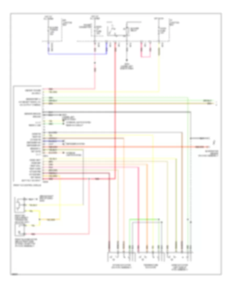
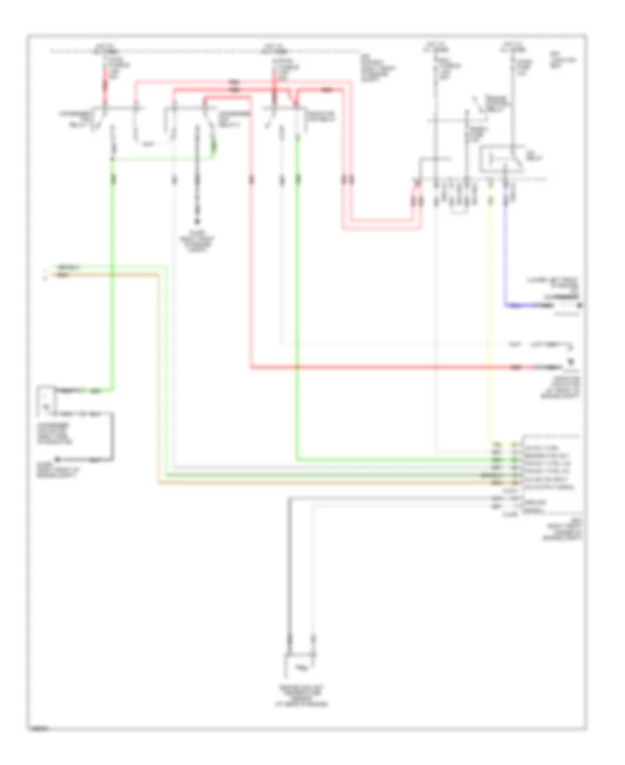
Automatic A/C Wiring Diagram (1 of 2) for Hyundai Veracruz SE 2007


List of elements for Automatic A/C Wiring Diagram (1 of 2) for Hyundai Veracruz SE 2007:
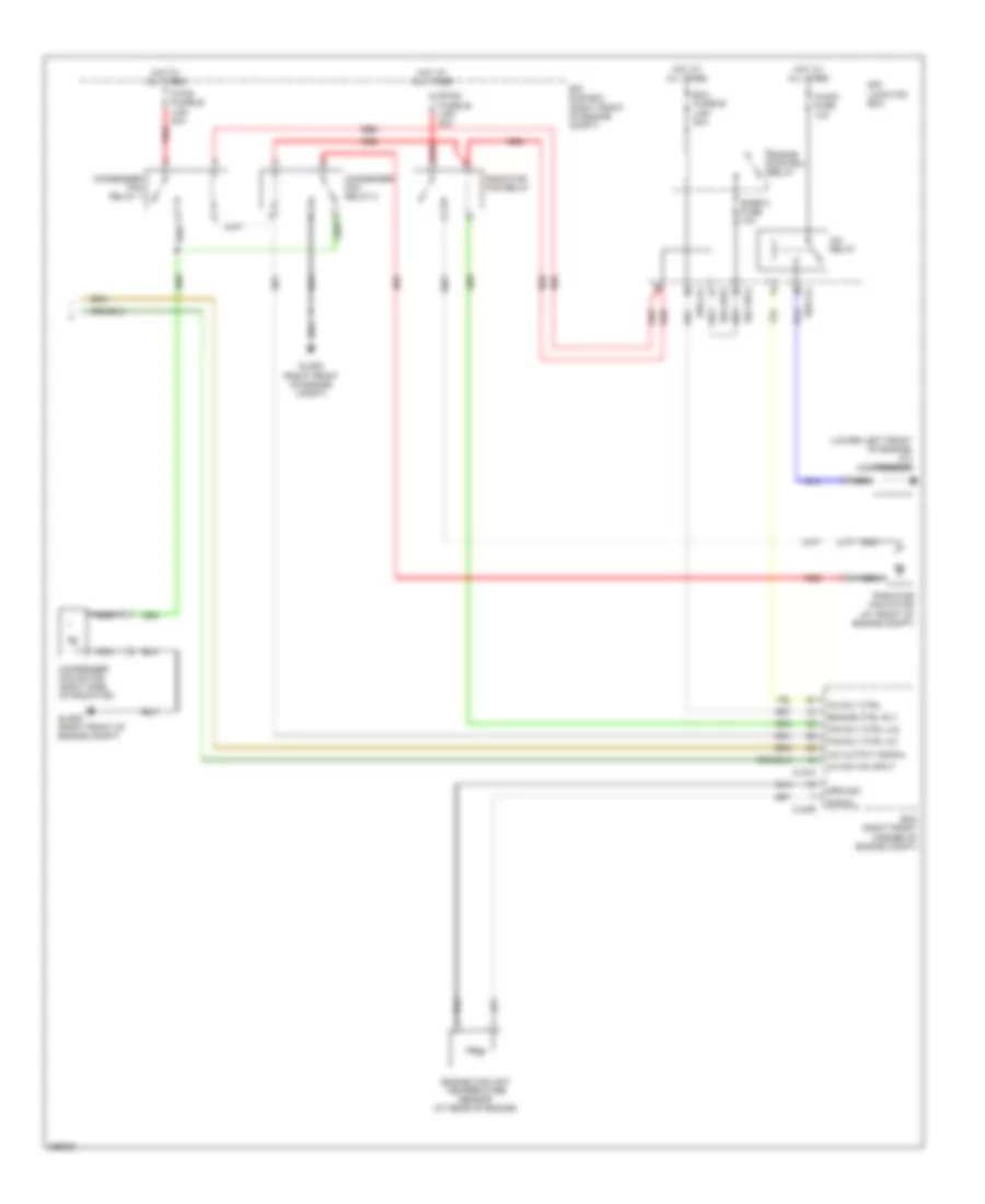
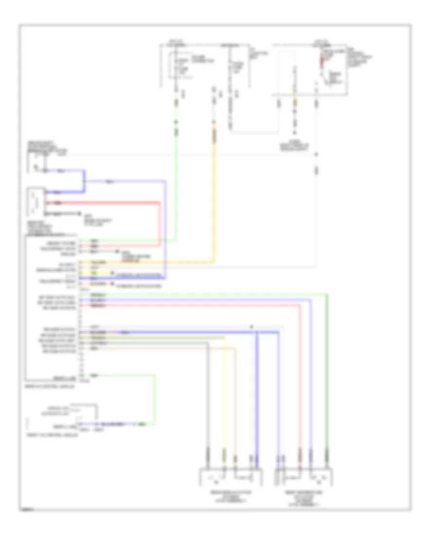
Automatic A/C Wiring Diagram (2 of 2) for Hyundai Veracruz SE 2007
List of elements for Automatic A/C Wiring Diagram (2 of 2) for Hyundai Veracruz SE 2007:
Heater Wiring Diagram for Hyundai Veracruz SE 2007
List of elements for Heater Wiring Diagram for Hyundai Veracruz SE 2007:
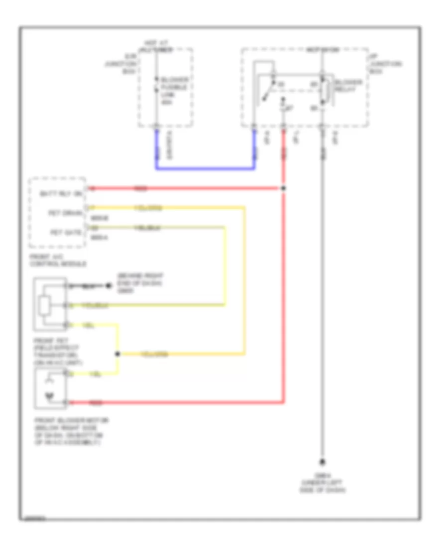
Manual A/C Wiring Diagram (1 of 2) for Hyundai Veracruz SE 2007
List of elements for Manual A/C Wiring Diagram (1 of 2) for Hyundai Veracruz SE 2007:
Manual A/C Wiring Diagram (2 of 2) for Hyundai Veracruz SE 2007
List of elements for Manual A/C Wiring Diagram (2 of 2) for Hyundai Veracruz SE 2007:
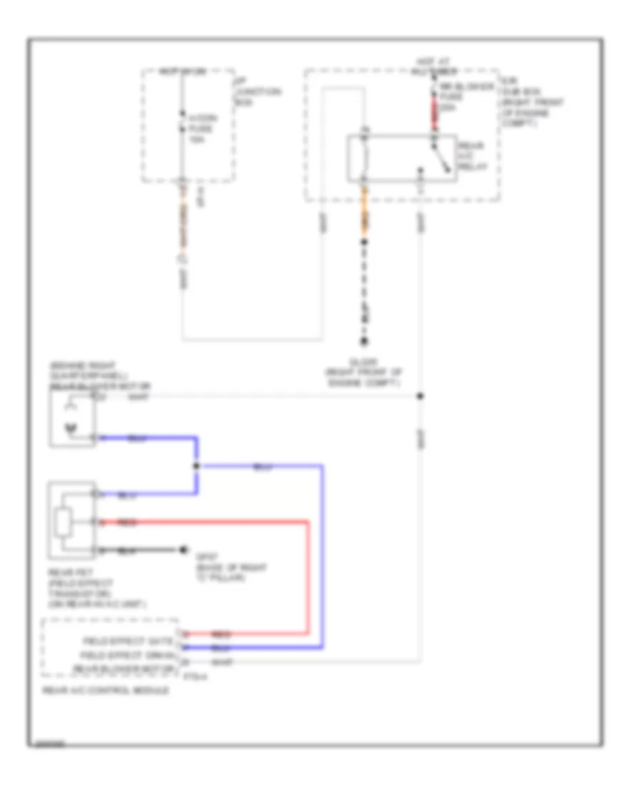
Rear A/C Wiring Diagram for Hyundai Veracruz SE 2007
List of elements for Rear A/C Wiring Diagram for Hyundai Veracruz SE 2007:
Rear Heater Wiring Diagram for Hyundai Veracruz SE 2007
List of elements for Rear Heater Wiring Diagram for Hyundai Veracruz SE 2007: