TRANSMISSION
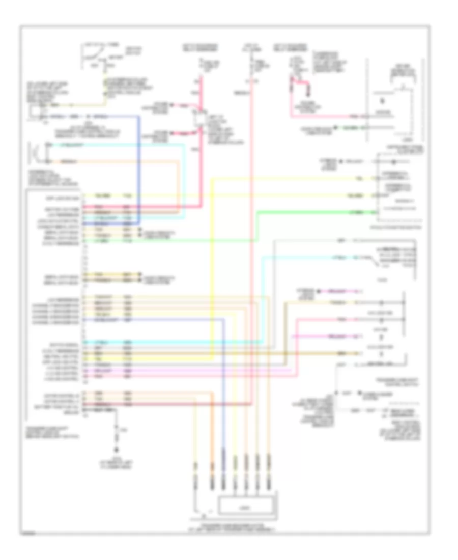
A/T Wiring Diagram (1 of 2) for Hummer H2 2008

List of elements for A/T Wiring Diagram (1 of 2) for Hummer H2 2008:
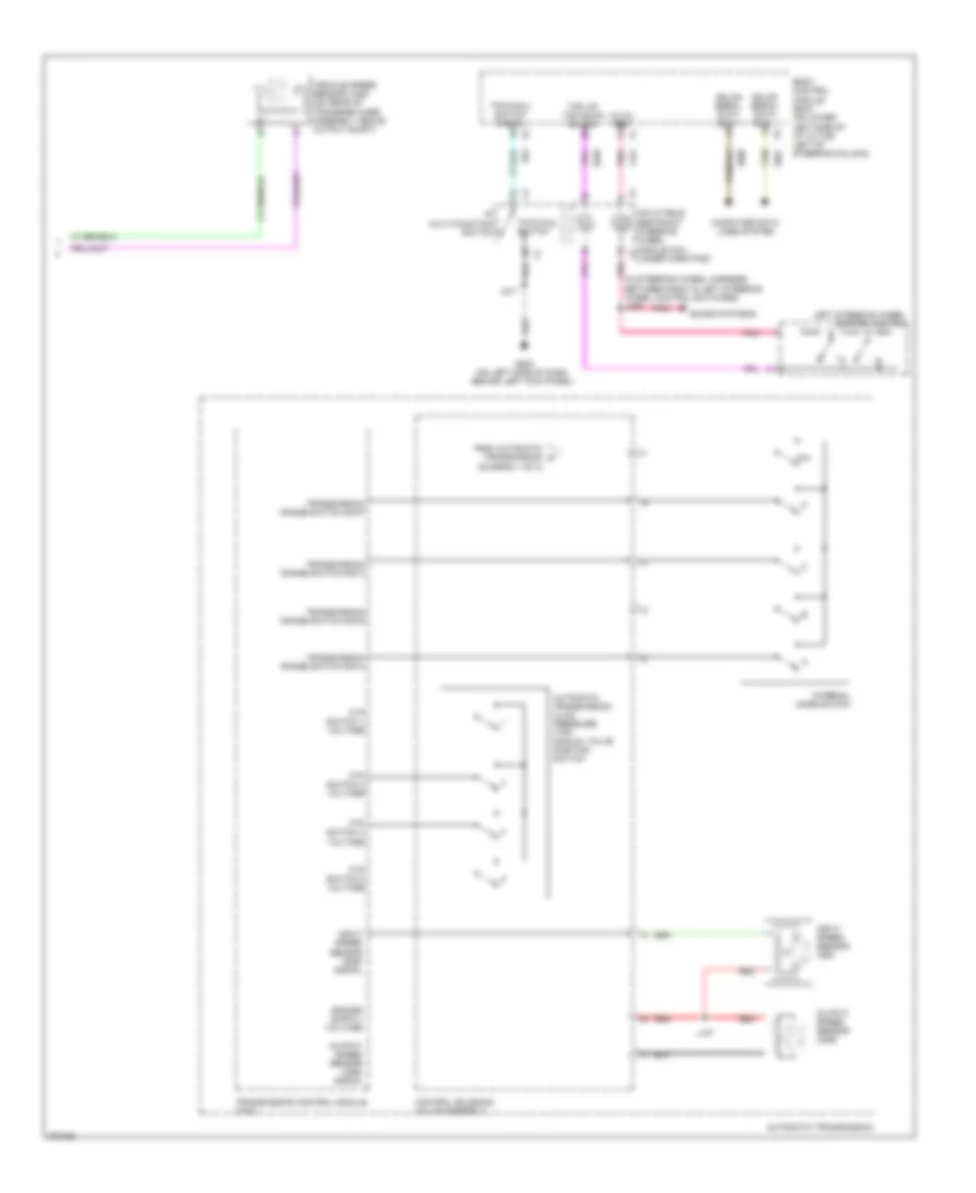
A/T Wiring Diagram (2 of 2) for Hummer H2 2008
List of elements for A/T Wiring Diagram (2 of 2) for Hummer H2 2008:
Transfer Case Wiring Diagram for Hummer H2 2008
List of elements for Transfer Case Wiring Diagram for Hummer H2 2008: