AIR CONDITIONING
Automatic A/C Wiring Diagram (1 of 3) for Buick Park Avenue Ultra 2004


List of elements for Automatic A/C Wiring Diagram (1 of 3) for Buick Park Avenue Ultra 2004:
- 5 volt ref
- A10
- A11
- A12
- Amb temp sig
- Ambient air temperature sensor (on center front of engine compt, on hood latch brace)
- B10
- B11
- B12
- Bat pos volt
- Blower spd ctrl
- C10
- C11
- C12
- C13
- C14
- C15
- C16
- Class 2 serial
- Clock sig
- Computer data lines system
- Cstr/ sbm fuse 10a
- D10
- D11
- D12
- D13
- D14
- D15
- D16
- Data sig
- G202 (left kick panel)
- Gnd
- Ground
- Hot at all times
- Hot in run
- Hvac control module
- Hvac fuse 10a
- I/p fuse block (behind glove box)
- Ign 3 volt
- Inside air temperature sensor (under left side of dash, near left center a/c vent)
- Inside temp sig
- Instrument panel integration module (ipm) (behind right side of dash, near rear of glove box)
- Interior lights system
- Lamp volt
- Left sun load sensor (on left side of dash, in defroster grille)
- Lft dr pos sig
- Lft solar sens
- Lft temp dr ctrl
- Ll temp sig
- Low ref
- Low rt temp sig
- Lower left air temperature sensor (on left side of dash, above sound insulator panel)
- Lower right air temperature sensor (on right side of dash, above sound insulator)
- Mode door ctrl
- Mode dr pos sig
- Nca
- Pass solar sens
- Recirc door ctrl
- Recirc dr pos sig
- Red
- Right air temperature switch assembly
- Right sun load sensor (on right side of dash, in defroster grille)
- Rt dr pos sig
- Rt temp dr ctrl
- Rt temp sig
- S213 (in dash harness, 44 cm from hvac control)
- S214 (in dash harness, 13 cm before i/p control module)
- Serial data
- Tan
- Up lft temp sig
- Up rt temp sig
- Upper left air temperature sensor (on left side of dash, near a/c vent)
- Upper right air temperature sensor (on right side of dash, near a/c vent)
- Vf dim sig
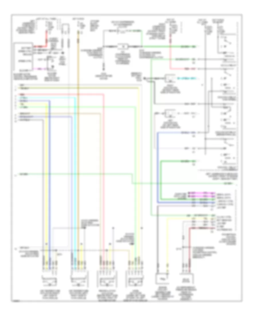
Automatic A/C Wiring Diagram (2 of 3) for Buick Park Avenue Ultra 2004
List of elements for Automatic A/C Wiring Diagram (2 of 3) for Buick Park Avenue Ultra 2004:
- (beneath battery tray) g105
- (hvac harness, 29 cm from mode actuator) s278
- (in body harness, 35 cm from g201)
- (in engine harness, 4 cm from powertrain control module harness breakout)
- (in hvac harness, 35.5 cm from mode actuator)
- (in hvac harness, 50.5 cm from mode actuator) s275
- (on a/c compressor) a/c compressor clutch
- 5v ref
- 87a
- A/c clu fuse 10a
- A/c clu relay
- A/c compressor clutch diode (near a/c compressor, in harness)
- A/c fuse 10a
- A/c press sig
- A/c refrigerant pressure sensor (near a/c compressor, on hose assembly)
- A10
- Air temperature actuator (left) (right side of hvac module)
- Air temperature actuator (right) (left side of hvac module)
- Battery
- Blo mot fuse 30a
- Blower motor (behind right side of dash)
- Blower motor control processor (near blower motor)
- Blower v+
- Clu rly ctrl
- Computer data lines system
- Cool- fan 1 fuse 30a
- Cool- fan 2 fuse 30a
- Coolfan 1 relay (low speed)
- Coolfan 2 relay (high speed)
- Coolfan s/p relay (series/parallel)
- D11
- E10
- Ect sens sig
- Engine coolant temperature (ect) sensor (under thermostat housing)
- F11
- G102 (near starter
- G201 (right kick panel)
- Ground
- H spd rly ctrl
- Hot at all times
- Hot in run
- Hot in run or start
- I/p fuse block (behind glove box)
- L spd rly ctrl
- Left cooling fan (on left rear side of radiator)
- Left underhood fuse block (on right front of engine compt, near battery)
- Low ref
- Mode actuator (under left side of dash, on left side of hvac module)
- Motor)
- Nca
- Powertrain control module (pcm) (in air cleaner housing)
- Recirculation actuator (behind right side of dash, right of blower motor)
- Red
- Right cooling fan (on right rear side of radiator)
- Right underhood fuse block (on right front of engine compt, forward of strut tower)
- S106 (in engine harness, 18 cm from a/c compressor clutch)
- S107 (in engine harness, 23 cm from a/c compressor clutch)
- S115
- S208
- S274
- Serial data
- Solid state
- Speed ctrl
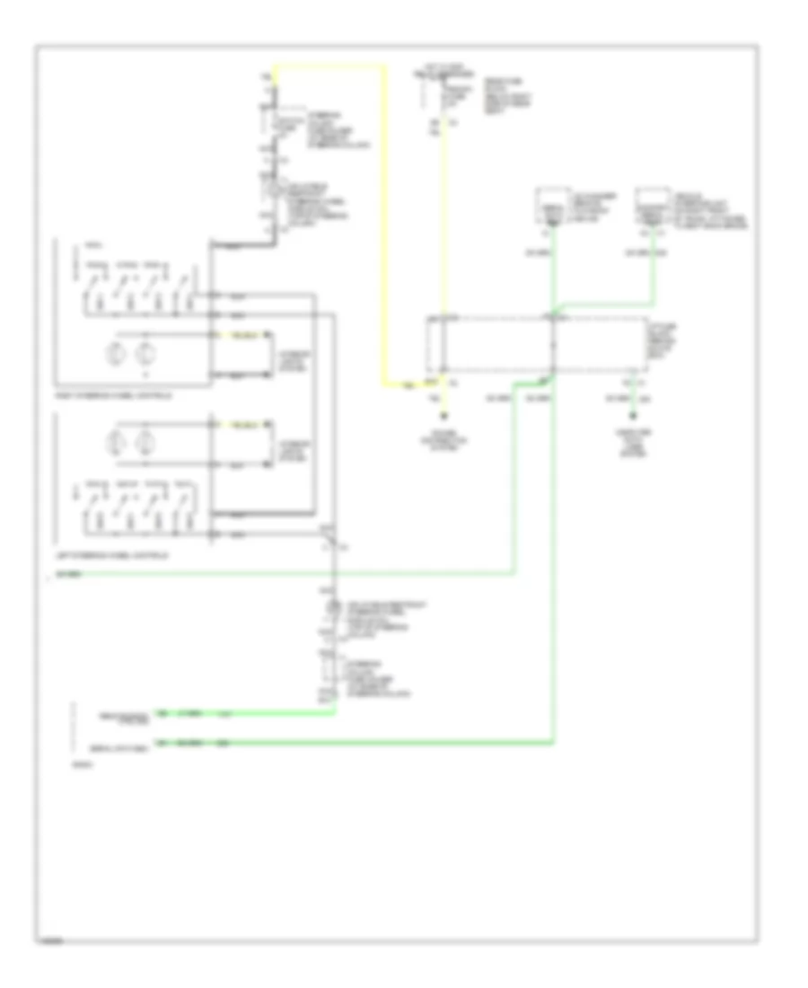
Automatic A/C Wiring Diagram (3 of 3) for Buick Park Avenue Ultra 2004
List of elements for Automatic A/C Wiring Diagram (3 of 3) for Buick Park Avenue Ultra 2004:
- B10
- B12
- C1 f5
- Cd changer remote playback device
- Comfort serial data
- Computer data lines system
- F8 c4
- Hot w/ rap relay energized
- I/p fuse block (behind glove box)
- Inflatable restraint steering wheel module coil (top of steering column)
- Interior lights system
- Left steering wheel controls
- Nca
- Power distribution system
- Radio
- Rdo/ph fuse 5a
- Rear fuse block (below right side of rear seat)
- Remote radio ctrl sig
- Right steering wheel controls
- Serial data e&c
- Steering column fuse holder (at base of steering column)
- Sw 1
- Sw 2
- Sw 3
- Sw 4
- Sw 5
- Sw 6
- Sw 7
- Sw 8
- Switch fuse 2a
- Vehicle interface unit (on right front of trunk, attached to seat back brace)
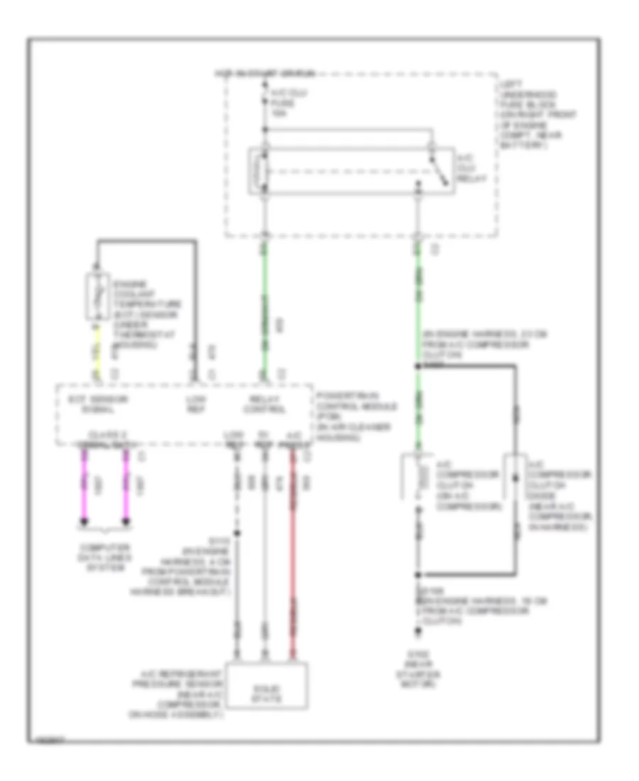
Compressor Wiring Diagram for Buick Park Avenue Ultra 2004
List of elements for Compressor Wiring Diagram for Buick Park Avenue Ultra 2004:
- (in engine harness, 18 cm from a/c compressor clutch)
- (in engine harness, 23 cm from a/c compressor clutch) s107
- 5v ref
- A/c clu fuse 10a
- A/c clu relay
- A/c compressor clutch (on a/c compressor)
- A/c compressor clutch diode (near a/c compressor, in harness)
- A/c press
- A/c refrigerant pressure sensor (near a/c compressor, on hose assembly)
- Class 2 serial data
- Computer data lines system
- Ect sensor signal
- Engine coolant temperature (ect) sensor (under thermostat housing)
- G102 (near starter motor)
- Hot in start or run
- Left underhood fuse block (on right front of engine compt, near battery)
- Low ref
- Nca
- Powertrain control module (pcm) (in air cleaner housing)
- Relay control
- S115 (in engine harness, 4 cm from powertrain control module harness breakout)
- Solid state

 Čeština
 Dansk
Dansk Deutsch
 English
 English
 Español
 Suomi
Suomi Français
 Français
 עברית
עברית Hrvatski
 Magyar
 Italiano
 日本語
日本語 한국어
한국어 Nederlands
 Polski
 Português
 Português
 Română
 Русский
 Slovenčina
 Slovenščina
 Svenska
 Türkçe
 中文 (中国)