AIR CONDITIONING
Automatic A/C Wiring Diagram for Ford Crown Victoria 2000


List of elements for Automatic A/C Wiring Diagram for Ford Crown Victoria 2000:
- (behind right kick panel, near door sill) g203
- (front of right front fender apron, right side of battery) g111
- (in 12a581 harness, near breakout to 12 pin in-line connector, left rear corner of engine compartment, rear of wheelwell)
- (in 14401 harness, near breakout to 3 pin in-line connector, lower right side of steering column, on connector bracket) s226
- (in 14401 harness, near breakout to glove box lamp)
- (not used)
- (red or nca)
- 4.6l natural gas
- 87a
- A/c clutch cycling pressure switch (in right rear of engine compartment, on a/c accumulator)
- A/c clutch output
- A/c compressor clutch coil (lower right front of engine)
- A/c high pressure cut out switch (in right side of engine compartment, near battery junction box)
- A/c wot cutout relay
- Amb temp sens input
- Ambient air temperature sensor (on front of upper radiator support)
- Battery
- Battery junction box (right front of engine compartment, behind battery)
- Blend door (cool)
- Blend door (heat)
- Blend door actuator (behind right side of dash, on top of a/c plenum)
- Blend door pot gnd
- Blend dr feedback
- Blower motor (on top right side of firewall)
- Blower motor speed controller (on right side of firewall, on evaporator assembly)
- Blower mtr output
- Blower speed ctrl
- C227
- C228
- C255
- Central junction box (below dash, left of steering column)
- Circuit breaker 17 30a
- Computer data lines system
- Cooling fan (front of engine compartment)
- Cooling fan high relay
- Cooling fan low relay
- E/m converter
- Electronic automatic temperature control (eatc) module (behind center of dash)
- Engine controls system
- English/ metric output
- Front panel illum
- Fuse 13 50a
- Fuse 15a
- Fuse 30a
- Ground
- High current relay center (right rear of engine compartment, behind battery junction box)
- Hot at all times
- Hot in run
- Ignition
- In car temp sens
- In-car temperature sensor (behind top center of dash)
- Inst illumination
- Instrument cluster (digital)
- Interior lights system
- Near door sill) g203
- Pcm power relay
- Powertrain control module (pcm) (in engine compartment, on left side of firewall)
- Red
- Reference voltage
- Relay center (left side of engine compartment)
- Relay signal
- S116 (in 14290 harness, near breakout to ground g111, front of right front fender apron, right side of battery)
- S129
- S139 (in 12a581 harness, on breakout for 8 pin in-line connector, left rear of engine compartment)
- S157 (in 12b637 harness, near breakout to a/c compressor clutch coil)
- S206
- S227 (in 14401 harness, near breakout to 3 pin in-line connector, lower right side of steering column, on connector bracket)
- S251 (in 14401 harness, in breakout to eatc)
- Scp data (-)
- Scp data bus (-)
- Sensor ground
- Sun load sensor (top right side of dash, above glove box)
- Sunload sens input
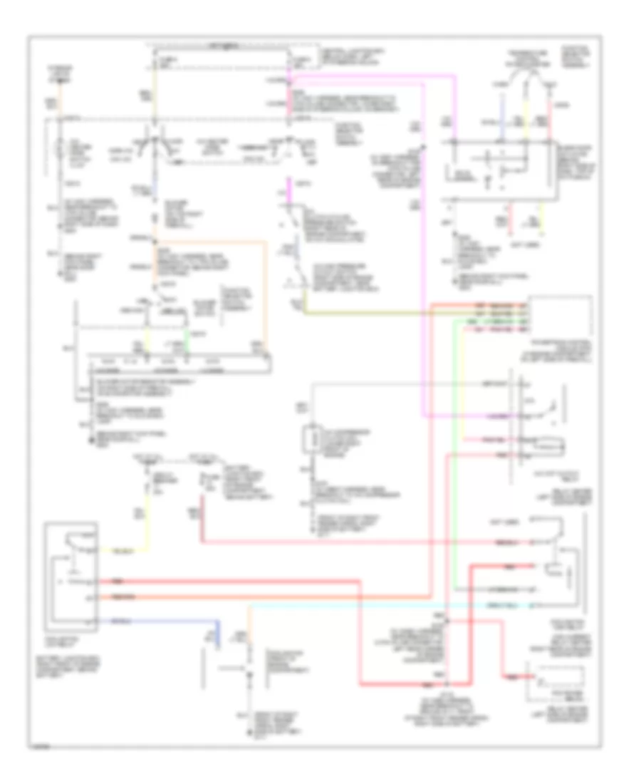
Manual A/C Wiring Diagram for Ford Crown Victoria 2000
List of elements for Manual A/C Wiring Diagram for Ford Crown Victoria 2000:
- (behind right kick panel, near door sill) g203
- (front of right front fender apron, right side of battery) g111
- (front of right front fender apron, right side of battery) g111
- (in 14401 harness, near breakout to 3 pin in-line connector, behind right side of dash) s204
- (not used)
- 0.5 ohms
- 1.3 ohms
- 87a
- A/c clutch cycling pressure switch (right rear of engine compartment, on a/c accumulator)
- A/c compressor clutch coil (lower right front of engine)
- A/c heater mode switch
- A/c high pressure cutout switch (right side of engine compartment, near battery junction box)
- A/c wot cutout relay
- A/c- heater mode switch illum
- Battery junction box (right front of engine compartment, behind battery)
- Blend door actuator (behind right side of dash, top of a/c plenum)
- Blower motor (on top right side of firewall)
- Blower motor resistor assembly (on right side of firewall, on evaporator assembly)
- Blower motor switch
- C2012
- C2018
- C2019
- C2020
- Central junction box (below dash, left of steering column)
- Circuit breaker 30a
- Cold
- Cooling fan (front of engine compartment)
- Cooling fan high relay
- Cooling fan low relay
- Def
- Floor
- Function selector switch assembly
- Fuse 5 15a
- Fuse 50a
- Fuse 9 30a
- High
- High current relay center (right rear of engine compartment)
- Hot at all times
- Hot in run
- Interior lights system
- Lamp)
- Low
- Max a/c
- Med high
- Med low
- Mix
- Norm a/c
- Off
- Pcm power relay
- Powertrain control module (pcm) (in engine compartment, on left side of firewall)
- Red
- Relay center (left side of engine compartment)
- S116 (in 14290 harness, near breakout to ground g111, front of right front fender apron, right side of battery)
- S129 (in 12a581 harness, near breakout to 12 pin in-line connector, left rear corner of engine compartment)
- S139 (in 12851 harness, on breakout for 8-pin in-line connector, left rear of engine compartment)
- S206 (in 14401 harness, near breakout to glove box lamp)
- S226 (in 14401 harness, near breakout to 3 pin in-line connector, lower right side of steering column, on bracket)
- S239 (in 14401 harness, near breakout to 1 pin in-line connector, behind right kick panel)
- Solid state
- Temperature control potentiometer
- Vent
- Warm

 Čeština
 Dansk
Dansk Deutsch
 English
 English
 Español
 Suomi
Suomi Français
 Français
 עברית
עברית Hrvatski
 Magyar
 Italiano
 日本語
日本語 한국어
한국어 Nederlands
 Polski
 Português
 Português
 Română
 Русский
 Slovenčina
 Slovenščina
 Svenska
 Türkçe
 中文 (中国)