CRUISE CONTROL
Cruise Control Wiring Diagram for Ford Explorer 1998
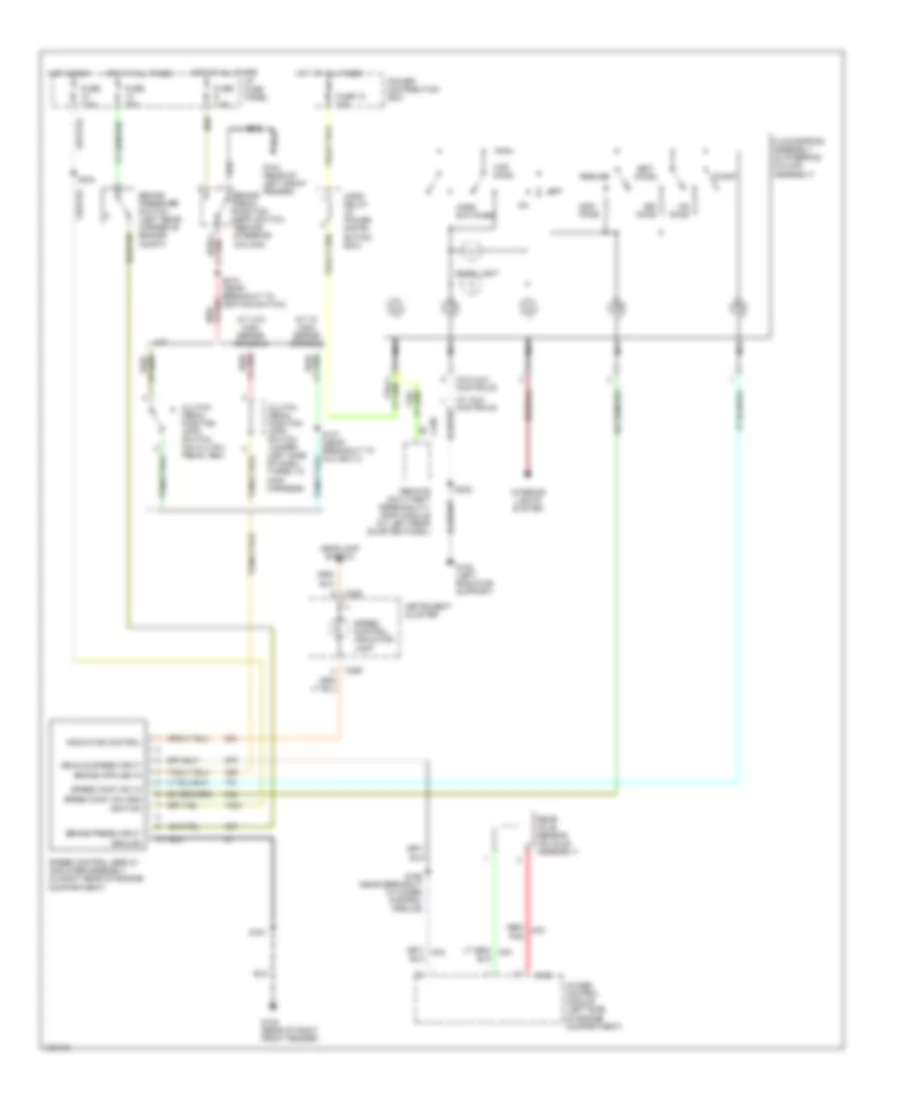
List of elements for Cruise Control Wiring Diagram for Ford Explorer 1998:
- (w/ aux controls)
- (w/o aux controls)
- 4wabs control module (left side of engine compartment)
- A/t w/ high series console
- A/t w/o high series console
- Accel
- Back light
- Brake pedal position (bpp) switch (behind steering column)
- Brake press input
- Brake pressure switch (left rear corner of engine compt)
- C186
- C286
- C338
- Clockspring assembly (in steering column assembly)
- Clutch pedal position (cpp) switch (on clutch pedal arm)
- Clutch pedal position (cpp) switch jumper (left side of dash, taped to main harness)
- Coast
- Fuse 10 15a
- Fuse 20a
- Fuse 7.5a
- G104 (rear of left front fender)
- G105 (rear of right front fender)
- G108 (left radiator support)
- Ground
- Headlamp switch
- Horn relay (in power distri- bution box)
- Horn switches
- Hot at all times
- Hot in run
- I/p fuse panel
- Ignition
- Indicator control
- Instrument cluster
- Interior lights system
- M/t
- Nca
- Off
- Ohms
- Pnk
- Power distribution box
- Rear axle sensor (on axle assembly)
- Red/
- Red/ lt grh
- Remote anti-theft personality (rap) module (at left rear quarter panel)
- Resume
- S161
- S168 (near breakout to 4wabs control module)
- S215 (near breakout to ignition switch)
- S230
- S232
- S244
- Set/
- Speed cont sw gnd
- Speed cont sw in
- Speed control indicator lamp
- Speed control servo/ amplifier assembly (in right rear of engine compartment)
- Vehicle speed input
 Čeština
 Dansk
Dansk Deutsch
 English
 English
 Español
 Suomi
Suomi Français
 Français
 עברית
עברית Hrvatski
 Magyar
 Italiano
 日本語
日本語 한국어
한국어 Nederlands
 Polski
 Português
 Português
 Română
 Русский
 Slovenčina
 Slovenščina
 Svenska
 Türkçe
 中文 (中国)
 Ελληνικά