DEFOGGERS
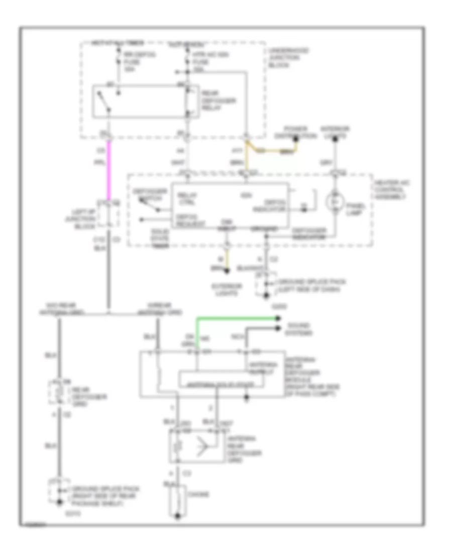
Defogger Wiring Diagram for Oldsmobile Alero GX 2000
List of elements for Defogger Wiring Diagram for Oldsmobile Alero GX 2000:
- A c1
- A c2
- A11
- Antenna output
- Antenna rear defogger grid
- Antenna solid state
- Antenna/ rear defogger module (right rear side of pass compt)
- C c2
- C1 c2
- C2 j
- C3 c12
- Choke
- Defog indicator
- Defog request
- Defogger indicator
- Defogger switch
- Dim input
- Exterior lights
- G202
- G313
- Ground
- Ground splice pack (left side of dash)
- Ground splice pack (right side of rear package shelf)
- Heater a/c control assembly
- Hot at all times
- Hot in run
- Htr a/c ign fuse 10a
- Ign
- Interior lights
- K c2
- Left i/p junction block
- Nca
- Panel lamp
- Power distribution
- Rear defogger grid
- Rear defogger relay
- Relay ctrl
- Rr defog fuse 30a
- Solid state timer
- Sound systems
- Underhood junction block
- W/o rear antenna grid
- W/rear antenna grid
 Čeština
 Dansk
Dansk Deutsch
 English
 English
 Español
 Suomi
Suomi Français
 Français
 עברית
עברית Hrvatski
 Magyar
 Italiano
 日本語
日本語 한국어
한국어 Nederlands
 Polski
 Português
 Português
 Română
 Русский
 Slovenčina
 Slovenščina
 Svenska
 Türkçe
 中文 (中国)
 Ελληνικά