
 Čeština
 Dansk
Dansk Deutsch
 English
 English
 Español
 Suomi
Suomi Français
 Français
 עברית
עברית Hrvatski
 Magyar
 Italiano
 日本語
日本語 한국어
한국어 Nederlands
 Polski
 Português
 Português
 Română
 Русский
 Slovenčina
 Slovenščina
 Svenska
 Türkçe
 中文 (中国)

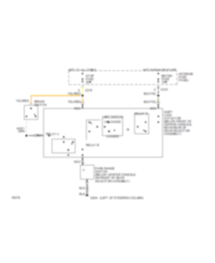
SHIFT INTERLOCKS
Shift Interlock Wiring Diagram for Ford Probe 1994
List of elements for Shift Interlock Wiring Diagram for Ford Probe 1994:

ANTI-LOCK BRAKESCOMPUTER DATA LINESDEFOGGERSANTI-THEFTEXTERIOR LIGHTSCRUISE CONTROLENGINE PERFORMANCEHORNHEADLIGHTSGROUND DISTRIBUTIONINSTRUMENT CLUSTERPOWER DOOR LOCKSINTERIOR LIGHTSPOWER TOP/SUNROOFPOWER SEATSPOWER MIRRORSPOWER ANTENNAPOWER WINDOWSSHIFT INTERLOCKSPOWER DISTRIBUTIONRADIOSUPPLEMENTAL RESTRAINTSSTARTING/CHARGINGTRANSMISSIONWIPER/WASHER