STARTING/CHARGING
Charging Wiring Diagram for Oldsmobile Intrigue GL 2002


List of elements for Charging Wiring Diagram for Oldsmobile Intrigue GL 2002:
- (not used)
- Battery
- Charge warning indicator (red)
- Class 2 serial data line
- Cluster fuse 10a
- Computer data lines
- Fusible link (10 ga- red)
- G100 (right side of engine compt, at base of battery)
- G110 (front side of engine block, near transmission bell housing)
- Gen fuse 10a
- Generator field duty cycle signal
- Generator l
- Generator turn on signal
- Hot at all times
- Hot in run, bulb test or start
- I/p fuse block (behind right side of dash, in right door opening)
- Ignition
- Instrument panel cluster (ipc)
- P b+
- Pnk
- Powertrain control module (pcm) (left front side of engine compartment, in air cleaner assembly)
- Red
- Regular ignition
- Remote battery stud
- Serial data from pcm
- Splice pack (sp205) (below dash, taped in harness, right side of steering column)
- Starter solenoid
- Underhood fuse block (mounted to right strut tower)
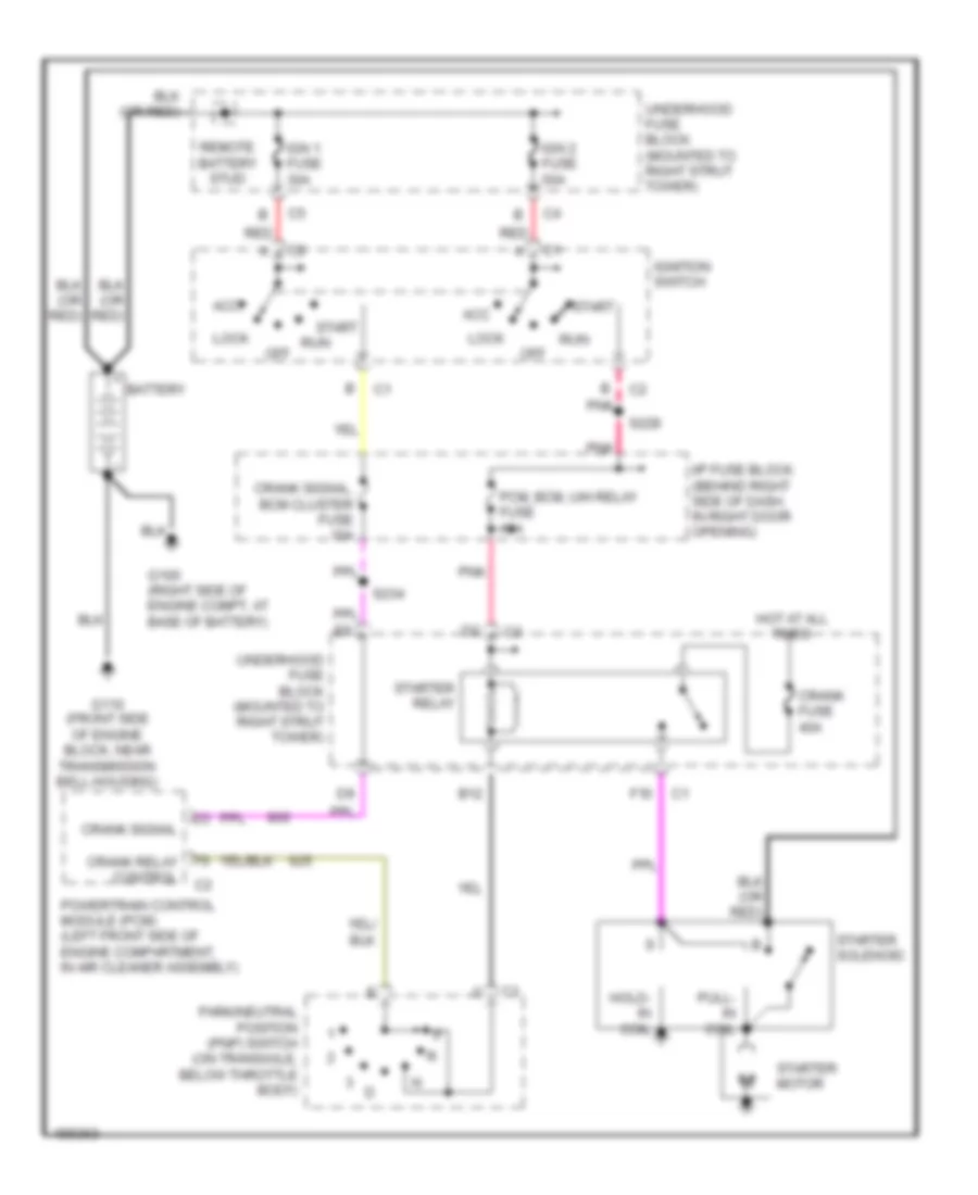
Starting Wiring Diagram, Early Production for Oldsmobile Intrigue GL 2002
List of elements for Starting Wiring Diagram, Early Production for Oldsmobile Intrigue GL 2002:
- Acc
- B12
- Battery
- Crank fuse 40a
- Crank relay control
- Crank signal
- Crank signal, bcm cluster fuse 10a
- F10
- G100 (right side of engine compt, at base of battery)
- G110 (front side of engine block, near transmission bell housing)
- Hold- in coil
- Hot at all times
- I/p fuse block (behind right side of dash, in right door opening)
- Ign 1 fuse 30a
- Ign 2 fuse 50a
- Ignition switch
- Lock
- Off
- Park/neutral position (pnp) switch (on transaxle, below throttle body)
- Pcm, bcm, u/h relay fuse 10a
- Pnk
- Powertrain control module (pcm) (left front side of engine compartment, in air cleaner assembly)
- Pull- in coil
- Red
- Remote battery stud
- Run
- S228
- S234
- Start
- Starter motor
- Starter relay
- Starter solenoid
- Underhood fuse block (mounted to right strut tower)
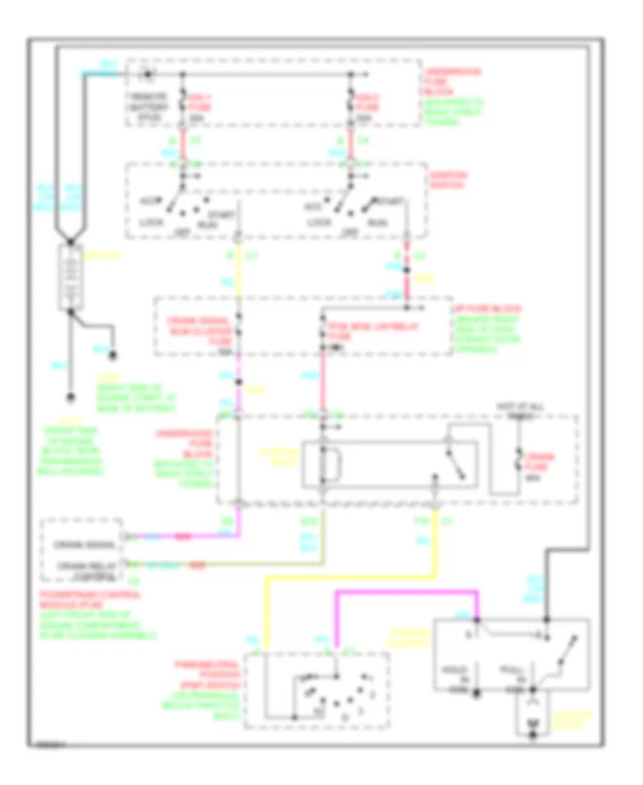
Starting Wiring Diagram, Late Production for Oldsmobile Intrigue GL 2002
List of elements for Starting Wiring Diagram, Late Production for Oldsmobile Intrigue GL 2002:
- Acc
- B12
- Battery
- Crank fuse 40a
- Crank relay control
- Crank signal
- Crank signal, bcm cluster fuse 10a
- F10
- G100 (right side of engine compt, at base of battery)
- G110 (front side of engine block, near transmission bell housing)
- Hold- in coil
- Hot at all times
- I/p fuse block (behind right side of dash, in right door opening)
- Ign 1 fuse 30a
- Ign 2 fuse 50a
- Ignition switch
- Lock
- Off
- Park/neutral position (pnp) switch (on transaxle, below throttle body)
- Pcm, bcm, u/h relay fuse 10a
- Pnk
- Powertrain control module (pcm) (left front side of engine compartment, in air cleaner assembly)
- Pull- in coil
- Red
- Remote battery stud
- Run
- S228
- S234
- Start
- Starter motor
- Starter relay
- Starter solenoid
- Underhood fuse block (mounted to right strut tower)

 Čeština
 Dansk
Dansk Deutsch
 English
 English
 Español
 Suomi
Suomi Français
 Français
 עברית
עברית Hrvatski
 Magyar
 Italiano
 日本語
日本語 한국어
한국어 Nederlands
 Polski
 Português
 Português
 Română
 Русский
 Slovenčina
 Slovenščina
 Svenska
 Türkçe
 中文 (中国)