SUPPLEMENTAL RESTRAINTS
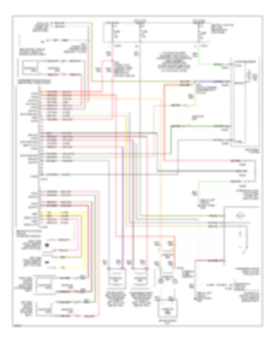
Supplemental Restraints Wiring Diagram for Ford Thunderbird 2005
List of elements for Supplemental Restraints Wiring Diagram for Ford Thunderbird 2005:
- (below left side of dash panel) g204
- (under left side of dash)
- 20-ja10
- 20-ja10c
- 30s-ja11
- 30s-ja33
- 30s-ja34
- 30s-ja37
- 30s-ja38
- 30s-ja8
- 31-ja10
- 31s-ja11
- 31s-ja14a
- 31s-ja33
- 31s-ja34
- 31s-ja37
- 31s-ja38
- 31s-ja8
- 4-ee1
- 4-ee6
- 7-ja39
- 7-ja40
- 8-ja13
- 8-ja26
- 8-ja56
- 9-ja26
- 9-ja39
- 9-ja40
- 91-ja14
- Abs control module (on right front of engine compartment)
- Air bag ind
- C175b
- C218b
- C220a
- C220b
- C270a
- C270c
- C283a
- C283b
- C283d
- C310a
- C310b
- Central junction box (cjb) (behind right kick panel)
- Chime
- Data bus
- Data link connector
- Deploy out
- Driver air bag unit
- Driver safety belt retractor pretensioner (at base of left "b" pillar, behind trim)
- Fuse 10a
- Fuse 5a
- Ground
- Hot in acc or run
- Hot in run
- Hot in run or start
- Instrument cluster
- Interior auxiliary junction box (under left side of dash)
- Iso
- Left side air bag module (left side of driver seat)
- Left side impact sensor (near base of left "a" pillar)
- Microprocessor
- Passenger air bag deactivation (pad) switch
- Passenger air bag module (behind right side of dash)
- Passenger safety belt retractor pretensioner (at base of right "b" pillar, behind trim)
- Pin shorting bars engaged when module connector is disconnected from harness (shorting bars are connected between pins: 3-4, 6-7, 20 & 21 conn. c310a 2-3, 5 & 6 conn. c310b)
- Powertrain control module (right rear of engine compt)
- Restraints control module
- Restraints control module (in center console)
- Right side air bag module (right side of passenger seat)
- Right side impact sensor (near base of right "b" pillar)
- S201 (in main harness, near breakout to c213)
- S217 (in body main harness, near breakout to c248)
- S302 (in body main harness, near breakout to restraints control module)
- Shorting bar
- Sig rtn
- Signal rtn
- Steering wheel assembly
- Switched gnd
- Vpwr
- Vref
 Čeština
 Dansk
Dansk Deutsch
 English
 English
 Español
 Suomi
Suomi Français
 Français
 עברית
עברית Hrvatski
 Magyar
 Italiano
 日本語
日本語 한국어
한국어 Nederlands
 Polski
 Português
 Português
 Română
 Русский
 Slovenčina
 Slovenščina
 Svenska
 Türkçe
 中文 (中国)
 Ελληνικά