AUTOMOTIVE ELECTRICIANS PORTAL

AIR CONDITIONING – Pontiac Grand Am GT 2000 – SYSTEM WIRING DIAGRAMS

AIR CONDITIONING

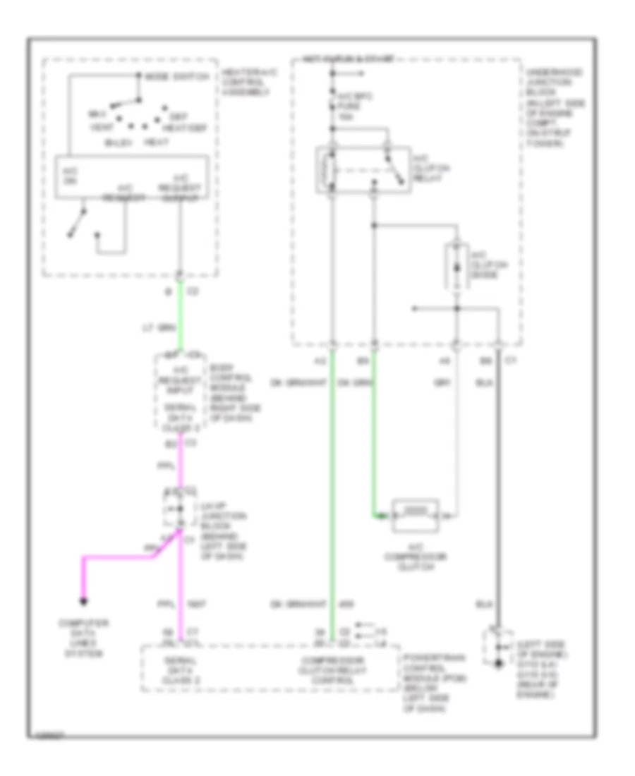
Compressor Wiring Diagram for Pontiac Grand Am GT 2000

Compressor Wiring Diagram for Pontiac Grand Am GT 2000 https://portal-diagnostov.com/license.html
https://portal-diagnostov.com/license.html Automotive Electricians Portal FZCO Automotive Electricians Portal FZCO
Αποκτήστε πρόσβαση σε όλα τα διαγράμματα καλωδίωσης αυτοκινήτουDownload PDF file

List of elements for Compressor Wiring Diagram for Pontiac Grand Am GT 2000:

  • (left side of engine) g112 (l4) g115 (v6) (rear of engine)
  • A/c bfc fuse 10a
  • A/c clutch diode
  • A/c clutch relay
  • A/c compressor clutch
  • A/c on
  • A/c request
  • A/c request input
  • A/c request output
  • Bi-lev
  • Body control module (behind right side of dash)
  • Compressor clutch relay control
  • Computer data lines system
  • Def
  • Heat
  • Heat/def
  • Heater-a/c control assembly
  • Hot in run & start
  • Lh i/p junction block (behind left side of dash)
  • Max
  • Mode switch
  • Powertrain control module (pcm) (below left side of dash)
  • Serial data class 2
  • Underhood junction block (in left side of engine compt, on strut tower)
  • Vent

Manual A/C Wiring Diagram for Pontiac Grand Am GT 2000

Manual AC Wiring Diagram for Pontiac Grand Am GT 2000 https://portal-diagnostov.com/license.html
https://portal-diagnostov.com/license.html Automotive Electricians Portal FZCO Automotive Electricians Portal FZCO
Αποκτήστε πρόσβαση σε όλα τα διαγράμματα καλωδίωσης αυτοκινήτουDownload PDF file

List of elements for Manual A/C Wiring Diagram for Pontiac Grand Am GT 2000:

  • (l4)
  • (v6)
  • A engine coolant temperature (ect) sensor (rear of engine) b
  • A/c
  • A/c clutch diode
  • A/c clutch relay
  • A/c compressor clutch
  • A/c disable
  • A/c on
  • A/c request
  • A/c request input
  • A/c request output
  • A10
  • Air temperature actuator (in center console)
  • Battery voltage
  • Bi-lev
  • Blower motor
  • Blower motor relay
  • Blower resistor assembly (below right side of dash)
  • Blower switch
  • Body control module (behind right side of dash)
  • C10
  • Compressor clutch relay control
  • Computer data lines system
  • Cool fan 1 fuse 30a
  • Cool fan 2 fuse 15a
  • D10
  • D11
  • Def
  • Def on
  • Defogger system
  • Ect sensor
  • Engine controls system
  • Exterior lights system
  • F11
  • Fan control relay 1
  • Fan control relay 2
  • G112 (l4) (left side of engine) g115 (v6) (rear of engine)
  • G200 (upper left kick panel)
  • G201 (right side of dash)
  • Gnd
  • Ground
  • Heat
  • Heat/def
  • Heater command output
  • Heater-a/c control assembly
  • Hi blo mot fuse 30a
  • High
  • Hot at all times
  • Hot in run
  • Hot in run & start
  • Htr-a/c ign fuse 10a
  • Ign
  • Interior lights system
  • Ipc/hvac batt fuse 10a
  • Lh cooling fan motor
  • Lh fan control
  • Lh i/p junction block (behind left side of dash)
  • Low
  • Max
  • Mode control relay
  • Mode request
  • Mode switch
  • Off
  • Olds only
  • Osa
  • Osa on
  • Osa request
  • Powertrain control module (pcm) (below left side of dash)
  • Rec
  • Rec on
  • Rec request
  • Rh cooling fan motor
  • Rh fan control
  • Rh i/p junction block (behind right side of dash)
  • S901
  • Sensor ground
  • Serial data class 2
  • Step dim input
  • Tan
  • Temp request input
  • Underhood junction block (in left side of engine compartment, on strut tower)
  • Vent