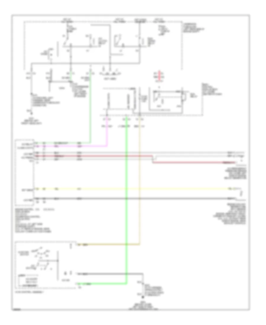
AIR CONDITIONING
Compressor Wiring Diagram for Saturn Ion Red Line 2007
List of elements for Compressor Wiring Diagram for Saturn Ion Red Line 2007:
- (not used)
- +5v
- 2.0l
- 2.2l & 2.4l
- A/c clutch relay
- A/c compressor clutch (at lower left front of engine)
- A/c diode
- A/c fuse 5 10a
- A/c ind
- A/c on/off
- A/c press
- A/c refrigerant pressure sensor (on lower left side of engine, below generator)
- A/c relay
- A/c request
- A/c switch
- A10
- Aa1
- Aa2
- Aa3
- Aa4
- B11
- Body control module (bcm) (at lower center of dash)
- Class 2 data
- Ect sens
- Engine control module (ecm) (2.2l & 2.4l) powertrain control module (pcm) (2.0l) (2.2l & 2.4l: at left side of engine compt) (2.0l: at rear of engine, near coolant overflow container)
- Engine coolant temperature (ect) sensor (2.0l: on top of engine, near right front corner of camshaft cover) (2.2l, 2.4l: on right rear side of engine, near exhaust manifold)
- F10
- G101 (behind left front headlight)
- G203 (behind lower left side of dash, left of steering column)
- Hot at all times
- Hot in run or start
- Hvac control assembly
- Hvac fan switch
- Hvac fuse 7.5a
- Ign 3 volt
- Logic
- Low ref
- Off
- Red
- Run (ign 3) fuse 48 30a
- Run relay
- Run relay ctrl
- Run/ crank relay
- S101 (in forward light harness, near underhood fuse block connector)
- S233 (in i/p harness, approximately 20 cm from radio c1 breakout)
- Underhood fuse block (left rear side of engine compt)
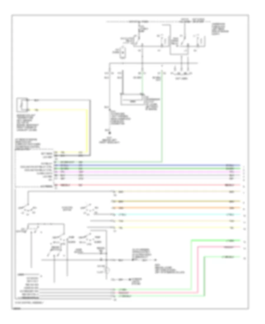
Manual A/C Wiring Diagram (1 of 2) for Saturn Ion Red Line 2007
List of elements for Manual A/C Wiring Diagram (1 of 2) for Saturn Ion Red Line 2007:
- (at rear of engine, near coolant overflow container) powertrain control module (pcm)
- (in i/p harness, approximately 20 cm from radio c1 breakout) s233
- (not used)
- +5v
- A/c clutch relay
- A/c compressor clutch (at lower left front of engine)
- A/c diode
- A/c fuse 5 10a
- A/c ind
- A/c press
- A/c relay
- A/c request sig
- A/c sig sw
- A/c switch
- A10
- Bi-lvl
- Blend
- Class 2 data
- Cooling fan relay ctrl
- Cooling fan s/p relay ctrl
- Def
- Ect sens
- Engine coolant temperature (ect) sensor (on top of engine, near right front corner of camshaft cover)
- F10
- G101 (behind left front headlight)
- G203 (behind lower left side of dash, left of steering column)
- Hot at all times
- Hot in run or start
- Htr
- Hvac control assembly
- Hvac fan switch
- Ign 3 volt
- Illum
- Interior lights system
- Logic
- Low ref
- Mode sw sig
- Mode switch
- Off
- Rec dr ctrl a
- Rec dr ctrl b
- Rec sw sig
- Recirc ind
- Recirc switch
- Run/ crank relay
- S101 (in forward light harness, near underhood fuse block connector)
- Tan
- Underhood fuse block (left rear side of engine compt)
- Vent
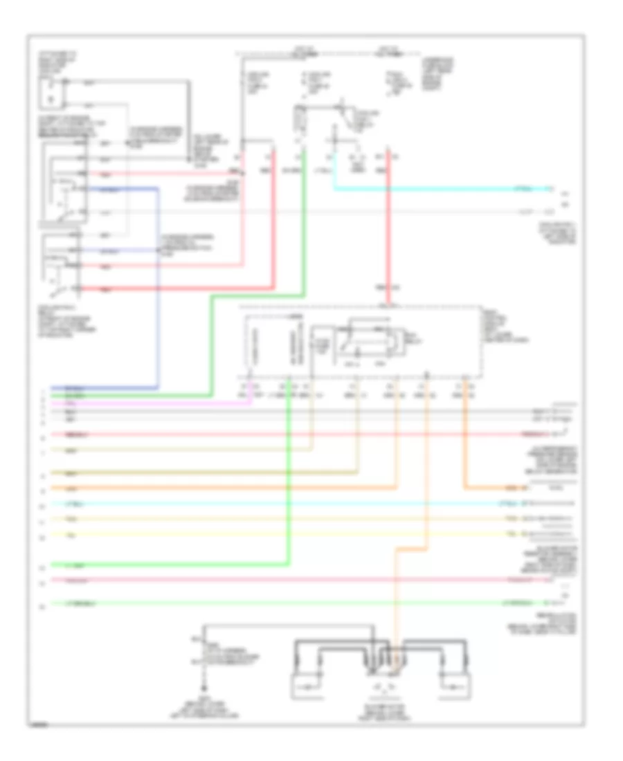
Manual A/C Wiring Diagram (2 of 2) for Saturn Ion Red Line 2007
List of elements for Manual A/C Wiring Diagram (2 of 2) for Saturn Ion Red Line 2007:
- (attached to right side of radiator) cooling fan 2
- (in engine harness, 1 cm from oil pressure switch) s160
- (in engine harness, 5 cm from starter cable breakout) s156
- (in front of engine compt, attached to top center of radiator) cooling fan s/p relay
- (not used)
- (on lower left rear of engine, above starter)
- 87a
- A/c refrigerant pressure sensor (on lower left side of engine, below generator)
- A/c request
- Aa1
- Aa2
- Aa3
- Aa4
- B11
- Blower motor (behind lower right side of dash)
- Blower motor resistor assembly (behind lower right side of dash, behind glove compt)
- Body control module (bcm) (at lower center of dash)
- Class 2 data
- Cooling fan 1 (attached to left side of radiator)
- Cooling fan 1 fuse 45 30a
- Cooling fan 1 relay
- Cooling fan 2 fuse 44 30a
- Cooling fan 2 relay (in front of engine compt, attached to top right corner of radiator)
- E1 c1
- G105
- G203 (behind lower left side of dash, left of steering column)
- Hot at all times
- Hvac fuse 7.5a
- Logic
- Nca
- Recirculation actuator (behind lower right side of dash, near "a" pillar)
- Red
- Run (ign 3) fuse 48 30a
- Run relay
- Run relay ctrl
- S158 (in engine harness, 6 cm from starter solenoid breakout)
- S260 (in i/p harness, 6.5 cm from blower motor breakout)
- Tan
- Underhood fuse block (left rear side of engine compt)

 Čeština
 Dansk
Dansk Deutsch
 English
 English
 Español
 Suomi
Suomi Français
 Français
 עברית
עברית Hrvatski
 Magyar
 Italiano
 日本語
日本語 한국어
한국어 Nederlands
 Polski
 Português
 Português
 Română
 Русский
 Slovenčina
 Slovenščina
 Svenska
 Türkçe
 中文 (中国)