ENGINE PERFORMANCE
3.0L TURBO DIESEL
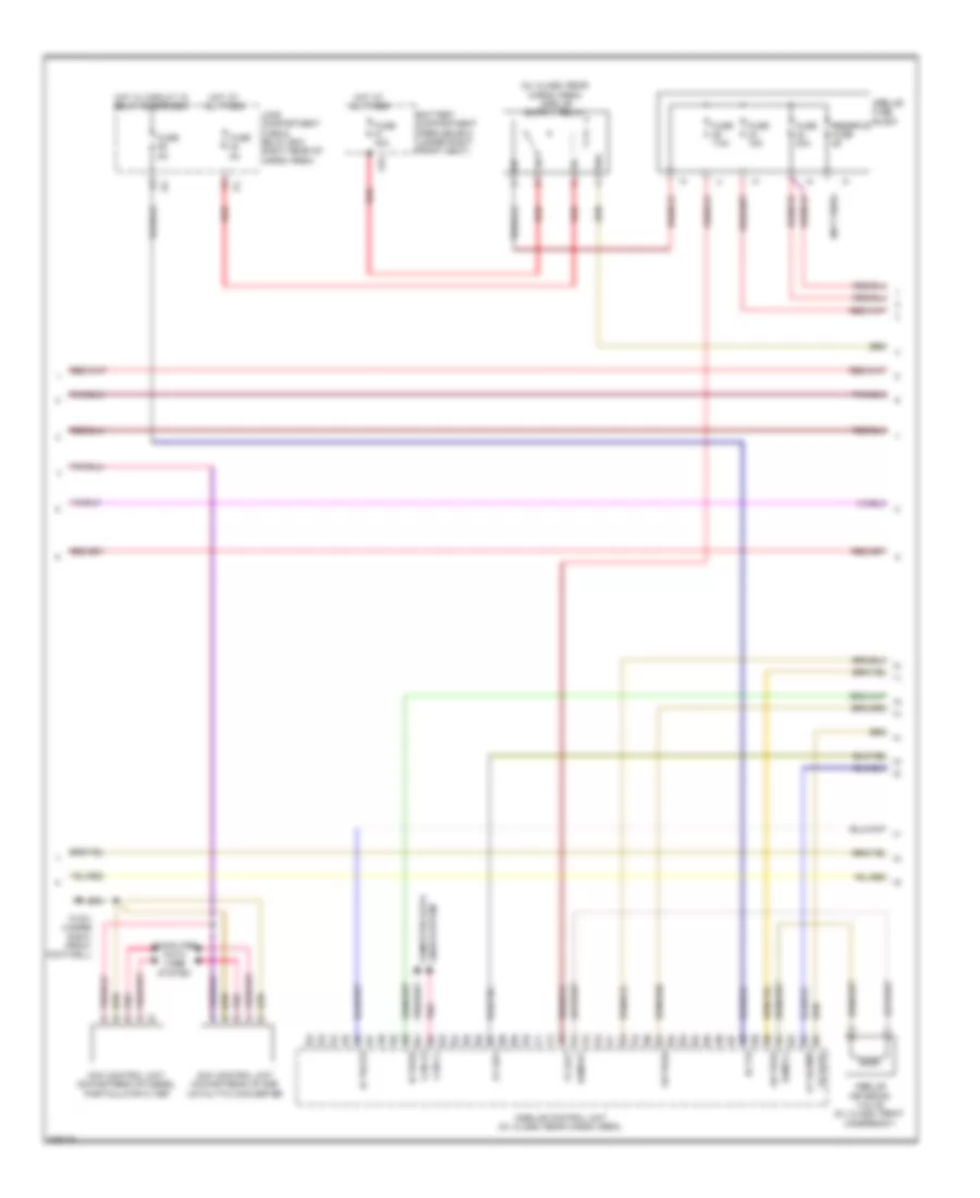
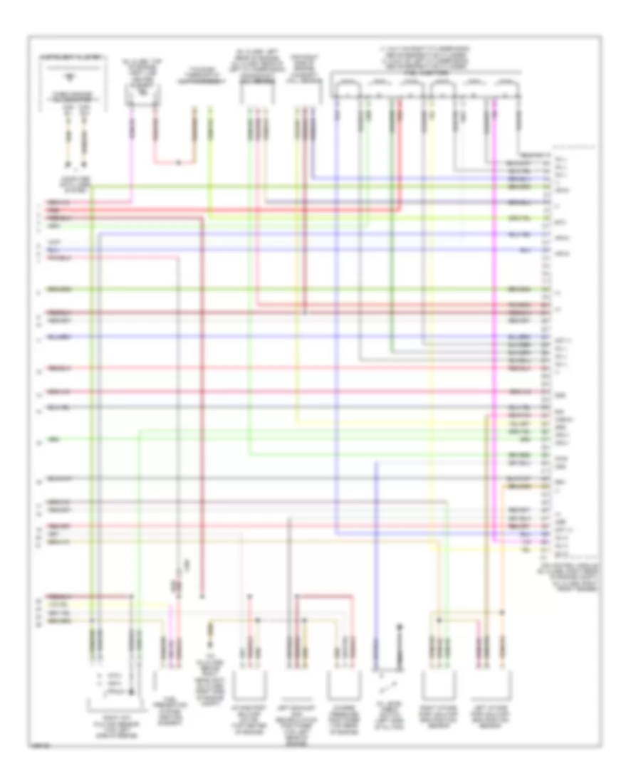
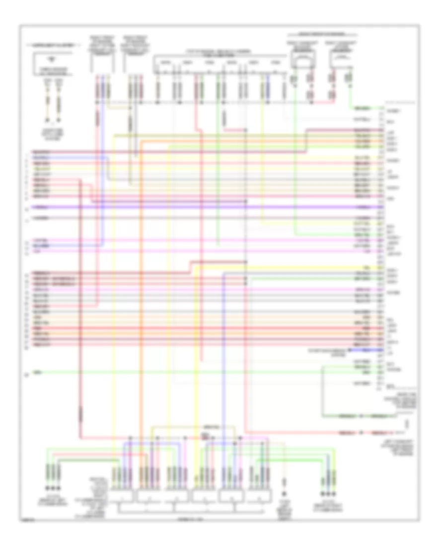
3.0L Turbo Diesel, Engine Performance Wiring Diagram (1 of 6) for Mercedes-Benz ML350 4Matic 2011
 https://portal-diagnostov.com/license.html
Automotive Electricians Portal FZCO
Automotive Electricians Portal FZCO
https://portal-diagnostov.com/license.html
https://portal-diagnostov.com/license.html
Automotive Electricians Portal FZCO
Automotive Electricians Portal FZCO
List of elements for 3.0L Turbo Diesel, Engine Performance Wiring Diagram (1 of 6) for Mercedes-Benz ML350 4Matic 2011:
- (ml-class: behind right headlight) (gl-class: right side of engine compt) w2
- 87d1
- 87d2
- Accelerator pedal sensor (top of accelerator pedal assembly)
- Air conditioning system
- Anr
- Can-c h
- Can-c l
- Can-i-h
- Can-i-l
- Cdi control module (gl class: right rear of engine compt) (ml class: right front fender)
- Computer data lines system
- Coolant circulation pump relay
- Crash
- E pwg1
- Engine circuit relay
- Engine compartment fuse & relay box (right side of engine compt)
- Exts3
- Exts4
- Front prefuse (right rear of engine compt)
- Fuel pump relay
- Fuse 100a
- Fuse 10a
- Fuse 15a
- Fuse 20a
- Fuse 25a
- Fuse 5a
- Ger
- Hot at all times
- Hot w/ starter relay energized
- Hrl
- Kpr
- Load compartment fuse & relay box (right side of cargo area)
- M pwg1
- Mr1
- Mr2
- Mr3
- Mr4
- Pnk
- Pressure differential sensor for diesel particulate filter for onboard diagnostics (obd) sensor
- Red
- Restraints system control module (under center console)
- Sig
- Starter relay
- Starting/charging system
- Temperature sensor upstream of diesel particulate filter (under right center of vehicle, in exhaust)
- Temperature sensor upstream of scr catalytic converter
- Transmission oil cooler circulation pump
- U pwg1
- W16/4 (right rear engine compt)
- X18/7
- X22/6
- X25/2-c1
- X25/2-c2
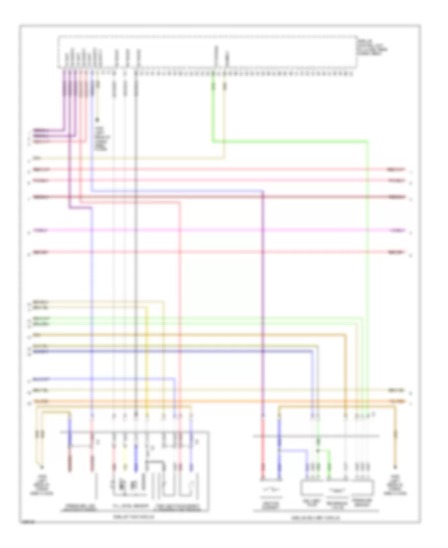
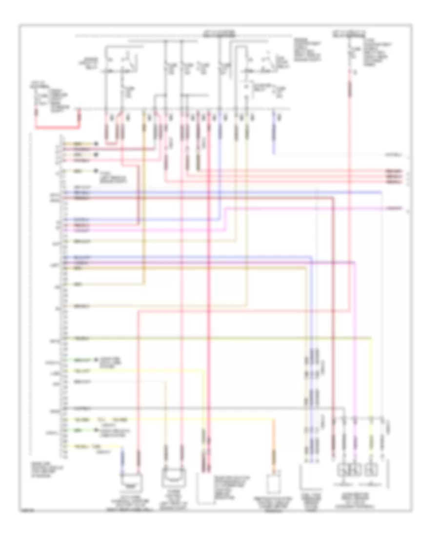
3.0L Turbo Diesel, Engine Performance Wiring Diagram (2 of 6) for Mercedes-Benz ML350 4Matic 2011
List of elements for 3.0L Turbo Diesel, Engine Performance Wiring Diagram (2 of 6) for Mercedes-Benz ML350 4Matic 2011:
- (not used)
- Battery compartment prefuse box (under right front seat)
- C81
- Can-i h
- Can-i l
- Computer data lines system
- Fuse 15a
- Fuse 20a
- Fuse 40a
- Fuse 5a
- Fuse 7.5a
- Gr pras
- Hot at all times
- Hot w/ circuit 15 relay energized
- Ia pras
- Ia trats
- Is t15
- Lines system computer data
- Load compartment fuse & relay box (right rear of cargo area)
- Nox control unit downstream of diesel particulate filter
- Nox control unit downstream of scr catalytic converter
- Os rarv
- Ot rapmp
- Ov rh1
- Pnk
- Ramvh1
- Ramvl1
- Red
- Reserve fuse
- Vv bat
- W15/1 (under right front footwell)
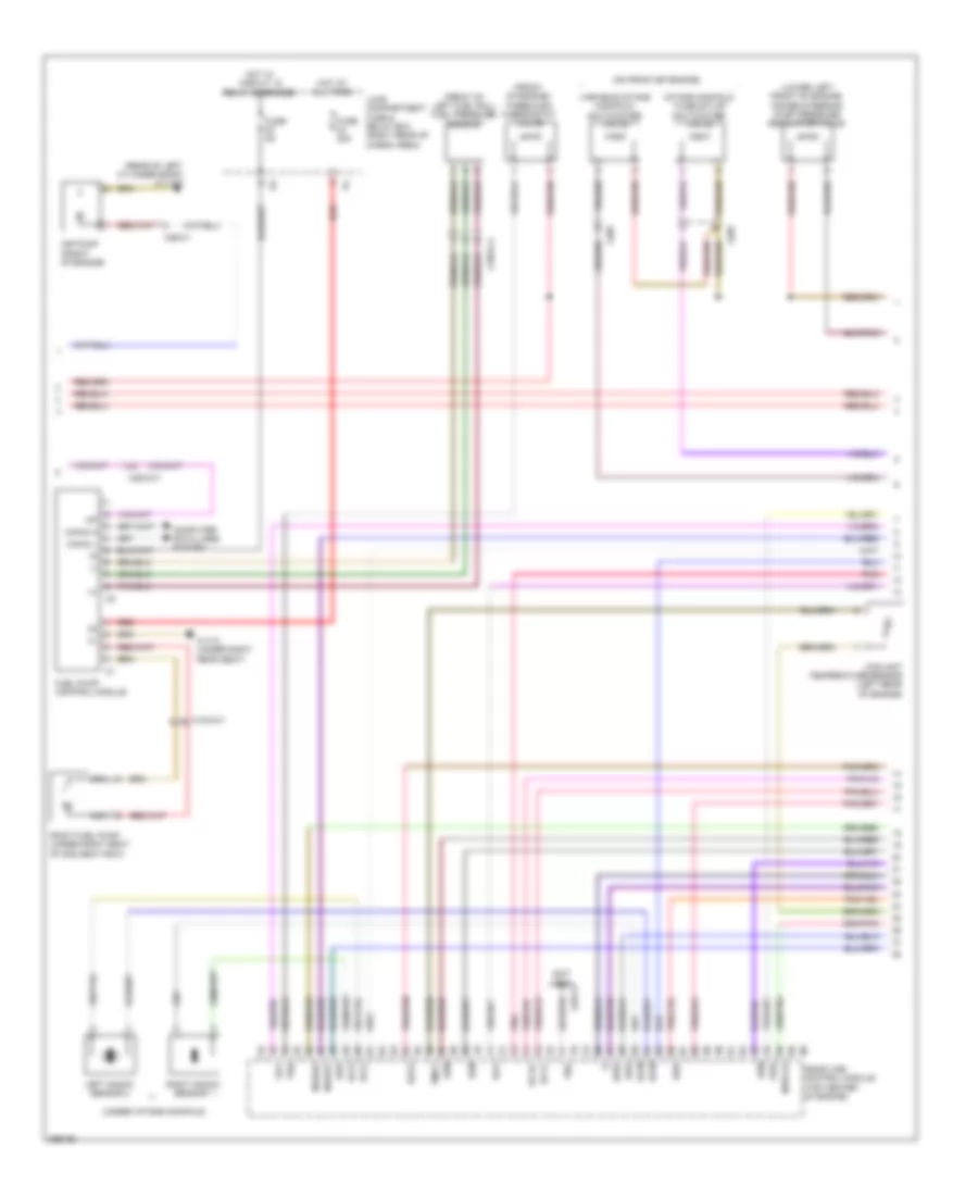
3.0L Turbo Diesel, Engine Performance Wiring Diagram (3 of 6) for Mercedes-Benz ML350 4Matic 2011
List of elements for 3.0L Turbo Diesel, Engine Performance Wiring Diagram (3 of 6) for Mercedes-Benz ML350 4Matic 2011:
- (left rear of
- Bf rals1
- Bf rals2
- Bf rals3
- Cargo area floor)
- Delivery pump
- Empty
- Fill level sensor
- Full
- Gg bat 2
- Heating element
- Os mrly
- Os raht1
- Os raht2
- Os raht3
- Pressure line heating element
- Pressure sensor
- Red
- Reserve
- Reversing valve
- Tank heating element & temperature sensor
- Vv 5vpras
- Vv bat
- W6/6
- W6/6 (left rear of cargo area floor)
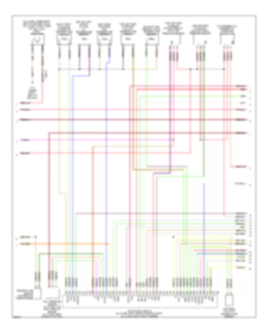
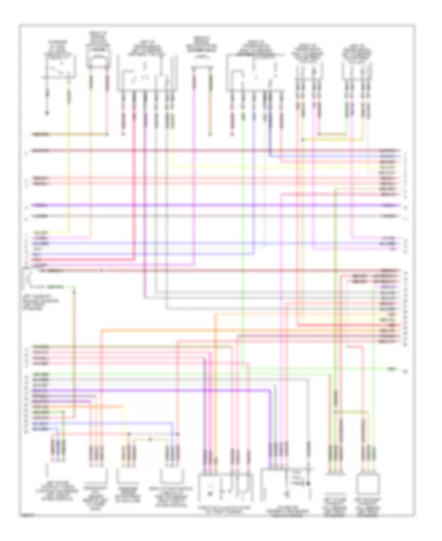
3.0L Turbo Diesel, Engine Performance Wiring Diagram (4 of 6) for Mercedes-Benz ML350 4Matic 2011
List of elements for 3.0L Turbo Diesel, Engine Performance Wiring Diagram (4 of 6) for Mercedes-Benz ML350 4Matic 2011:
- (+)
- (-)
- (at differential) differential pressure sensor (dpf)
- (bottom left side of oil pan) oil temperature sensor
- (center rear of engine) exhaust back pressure sensor
- (left front of engine) fuel temperature sensor
- (ml class: under right seat of 2nd seat row) (gl class: in right side of fuel tank) right fuel pump
- (right front of engine) charge air temperature sensor
- (top left side of engine) coolant temperature sensor
- (top left side of engine) downstream of air filter pressure sensor
- A-eka-r
- Cdi control module (gl class: right rear of engine compt) (ml class: right front fender)
- Cvh
- Drs
- Eka-a
- Exhaust gas recirculation temperature sensor
- Exts1
- Flwtr
- Iats3
- Inj h
- Kts-s
- Ldf-1
- Ldr
- Ls1
- Ls1hk
- Ls1p
- Lsh1hk
- Lshk
- Nca
- Rail pressure sensor (gl class: top right rear of engine) (ml class: rear of right fuel rail)
- Rds
- Red
- Sig
- T2-s
- Tag1
- Temperature sensor upstream of turbocharger
- Tmot
- Toel
- Upstream twc (kat) temperature sensor
- W17 (under right seat of 2nd row)
- X18/3-c1
- Zme+
3.0L Turbo Diesel, Engine Performance Wiring Diagram (5 of 6) for Mercedes-Benz ML350 4Matic 2011
List of elements for 3.0L Turbo Diesel, Engine Performance Wiring Diagram (5 of 6) for Mercedes-Benz ML350 4Matic 2011:
- (gl class: top of left cylinder bank)
- (gl class: top of right cylinder bank)
- (not used)
- (right front of engine)
- 1.zyl
- 2.zyl
- 3.zyl
- 4.zyl
- 5.zyl
- 6.zyl
- Charge pressure sensor (right front of engine)
- Consation sensor for fuel filter w/ heating element
- Cylinder glow plug 1
- Cylinder glow plug 2
- Cylinder glow plug 3
- Cylinder glow plug 4
- Cylinder glow plug 5
- Cylinder glow plug 6
- Glow time output stage (center front c1 of engine)
- Kfh21
- Kfhzz
- Left hot film maf sensor (gl class: top right side of engine)
- Lin
- Nca
- O2 sensor upstream twc (kat)
- Pressure regulator valve (top left front of engine)
- Quantity control valve
- Red
- Starting/ charging system
- Throttle valve actuator (on throttle body)
- W11
- W12
- Wss
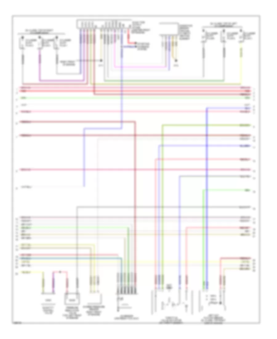
3.0L Turbo Diesel, Engine Performance Wiring Diagram (6 of 6) for Mercedes-Benz ML350 4Matic 2011
List of elements for 3.0L Turbo Diesel, Engine Performance Wiring Diagram (6 of 6) for Mercedes-Benz ML350 4Matic 2011:
- "check engine" mil indicator
- (+)
- (-)
- (1, 2 & 3: on right cylinder bank, above respective cylinder) (4, 5 & 6: on left cylinder bank, above respective cylinder) fuel injectors
- (gl class: left rear of engine) (ml class: rear of left cylinder bank) crankshaft hall sensor
- (gl class: top of engine) vent line heater element
- (top right side of engine) camshaft hall sensor
- A-eka-i
- Agr
- Can- b h
- Can- b l
- Cdi control module (gl class: right rear of engine compt) (ml class: right front fender)
- Charge pressure positioner (top rear of engine)
- Computer data lines system
- Dds
- Drs
- Drv
- Etc
- Fuel preheating system heating element
- Hfm-0
- Hfm-1
- Hfm-2
- Inj h
- Inj l
- Instrument cluster
- Intake port shutoff motor (top center of engine)
- Kwg
- Left exhaust gas recirculation positioner (top left rear of engine)
- Left intake port shutoff end position sensor
- Mot (+)
- Mot (-)
- Nca
- Ods
- Oil level check switch (left side of oil pan)
- Red
- Right hot film maf sensor (top left side of engine)
- Right intake port shutoff end position sensor
- Sig
- Two-disk thermostat heating element
- W2 (ml-class: behind right headlight) (gl-class: right side of engine compt)
- X18/7
3.5L
3.5L, Engine Performance Wiring Diagram (1 of 4) for Mercedes-Benz ML350 4Matic 2011
List of elements for 3.5L, Engine Performance Wiring Diagram (1 of 4) for Mercedes-Benz ML350 4Matic 2011:
- (right rear wheelwell)
- Accelerator pedal sensor (at top of accelerator pedal)
- Activated charcoal canister shutoff valve
- Air pump relay
- Akf
- Can-c h
- Can-c l
- Computer data lines system
- Electric suction fan engine & ac w/ integrated control (behind radiator)
- Engine circuit 87 relay
- Engine compartment fuse & relay box (right side of engine compt)
- Front prefuse (right rear of engine compt)
- Fuel tank pressure sensor (in fuel tank)
- Fuse 100a
- Fuse 10a
- Fuse 15a
- Fuse 40a
- Fuse 5a
- Hot at all times
- Hot w/ circuit 15 relay energized
- Hot w/ starter relay energized
- Load compartment fuse & relay box (right rear of cargo area)
- Lues
- Me-sfi (me) control module (top center of engine)
- Mr1
- Mr2
- Mr3
- Mr4
- Pnk
- Purge control valve (left front of engine compt)
- Red
- Restraints system control module (under center console)
- Slp
- Sp1m
- Sp1s
- Sp2m
- Sp2s
- Starter relay
- Usp1
- W16/3 (left rear of engine compt)
- X25/2-c1
- X25/2-c2
- X26-c2
3.5L, Engine Performance Wiring Diagram (2 of 4) for Mercedes-Benz ML350 4Matic 2011
List of elements for 3.5L, Engine Performance Wiring Diagram (2 of 4) for Mercedes-Benz ML350 4Matic 2011:
- (+)
- (-)
- (front of engine) three disk thermostat valve
- (front of left fuel rail) fuel pressure sensor
- (lower left front of engine) power steering pump pressure regulator valve
- (not used)
- (on front of engine)
- (rear of left cylinder bank) w11w2
- (under intake manifold)
- Air pump (front of engine)
- Brs
- Can-d h
- Can-d l
- Computer data lines system
- Coolant temperature sensor (left rear of engine)
- Dk s+
- Dk s-
- Dkp2
- Drs
- Fuel pump control module
- Fuse 20a
- Fuse 5a
- Hav
- Hfm
- Hot at all times
- Hot w/ circuit 15 relay energized
- Intake manifold tumble flap switchover valve
- Ks m
- Ks s
- Kwg
- Left knock sensor 2
- Load compartment fuse & relay box (right rear of cargo area)
- Me-sfi (me) control module (top center of engine)
- Nca
- Nwge1
- Nwge2
- Nws a2
- Oss
- Pnk
- Red
- Right fuel pump (under right seat of 2nd seat row)
- Right knock sensor 1
- Slv
- Ths
- Tmot
- Tna
- Variable intake manifold switchover valve
- W17/3 (under right rear seat)
- X18/3-c1
- X18/3-c4
- X205
- X25/2-c1
- X26-c1
- X26-c2
3.5L, Engine Performance Wiring Diagram (3 of 4) for Mercedes-Benz ML350 4Matic 2011
List of elements for 3.5L, Engine Performance Wiring Diagram (3 of 4) for Mercedes-Benz ML350 4Matic 2011:
- (front of engine) air pump switchover valve
- (in engine oil pan) oil level check switch
- (left of transmission) left o2 sensor downstream twc (kat)
- (left of transmission) left o2 sensor upstream twc (kat)
- (rear of engine) heating system shutoff valve
- (right of transmission) right o2 sensor downstream twc (kat)
- (right of transmission) right o2 sensor upstream twc (kat)
- Crankshaft hall sensor (rear of left cylinder bank)
- Intake air temperature sensor (rear of engine)
- Left camshaft exhaust solenoid (left front of engine)
- Left exhaust camshaft hall sensor (left front of engine)
- Left intake camshaft hall sensor (left front of engine)
- Left intake manifold tumble flap position sensor (left side of intake manifold)
- Nca
- Pnk
- Pressure sensor downstream of air filter
- Red
- Right intake manifold tumble flap position sensor (right side of intake manifold)
- Throttle valve actuator (on throttle body)
3.5L, Engine Performance Wiring Diagram (4 of 4) for Mercedes-Benz ML350 4Matic 2011
List of elements for 3.5L, Engine Performance Wiring Diagram (4 of 4) for Mercedes-Benz ML350 4Matic 2011:
- "check engine" mil indicator
- (+)
- (right front of engine)
- (right front of engine) right exhaust camshaft hall sensor
- (right front of engine) right intake camshaft hall sensor
- (top of engine, above cylinders) fuel injectors
- Can- b h
- Can- b l
- Computer data lines system
- Dkl
- Dkp m
- Ev1
- Ev2
- Ev3
- Ev4
- Ev5
- Hfm
- Ignition coils (1, 2 & 3: top of right cylinder bank) (4, 5 & 6: top of left cylinder cylinder bank)
- Instrument cluster
- Left camshaft intake solenoid (left front of engine)
- Lhp
- Lin
- Ls2hk
- Lsh1hk
- Lshk
- Me-sfi (me) control module (top center of engine)
- Nwae2
- Nwg m
- Nwga1
- Nws e2
- Nwsa 1
- Nwse 1
- Red
- Right camshaft exhaust solenoid
- Right camshaft intake solenoid
- Spark plugs
- Starting/charging system
- W11w1 (rear of right cylinder bank)
- W11w2 (rear of left cylinder bank)
- W16/3 (left rear of engine compt)
- Zue 1
- Zue 2
- Zue 3
- Zue 4
- Zue 5
- Zue 6

 Čeština
 Dansk
Dansk Deutsch
 English
 English
 Español
 Suomi
Suomi Français
 Français
 עברית
עברית Hrvatski
 Magyar
 Italiano
 日本語
日本語 한국어
한국어 Nederlands
 Polski
 Português
 Português
 Română
 Русский
 Slovenčina
 Slovenščina
 Svenska
 Türkçe
 中文 (中国)