ENGINE PERFORMANCE
3.5L
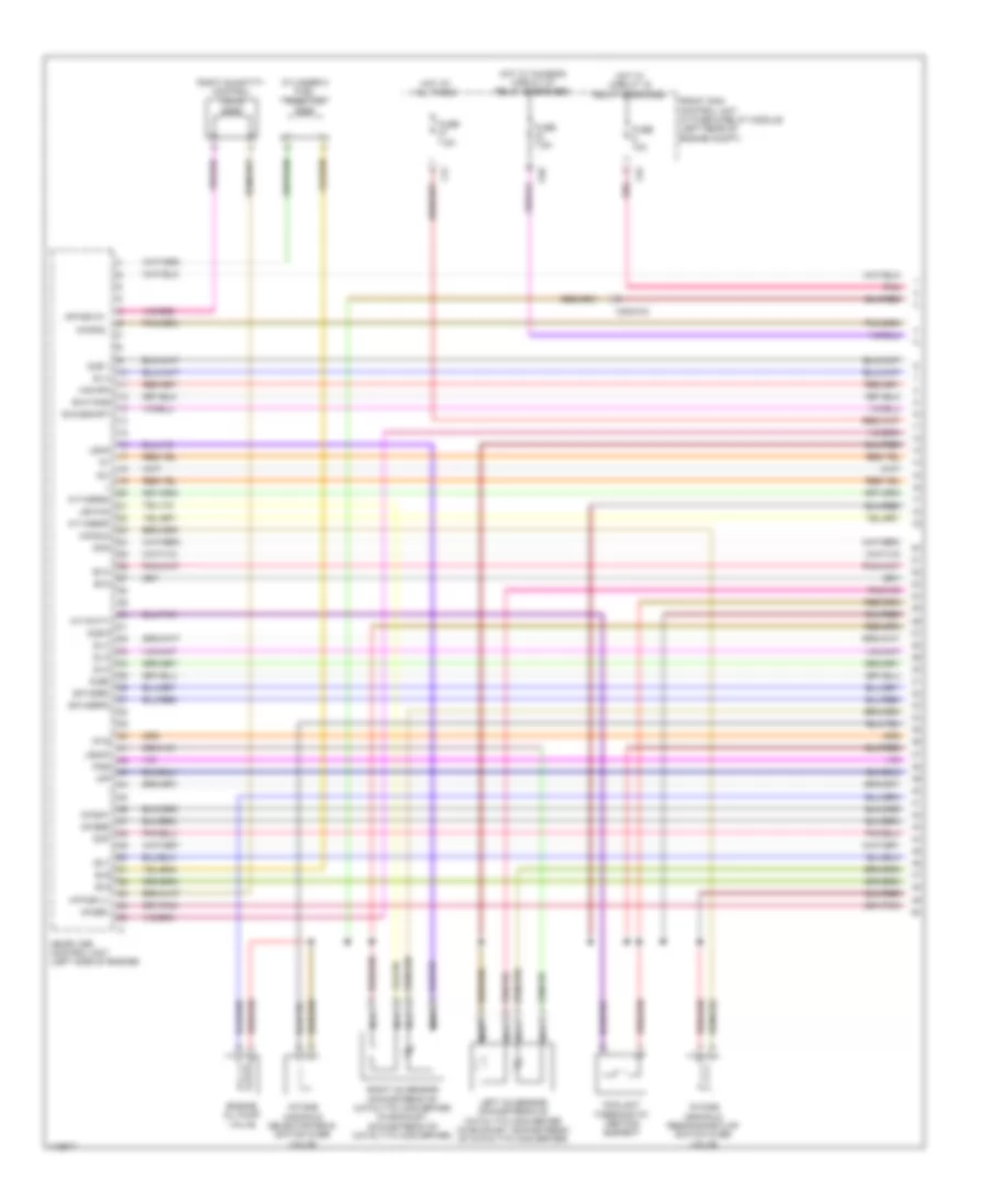
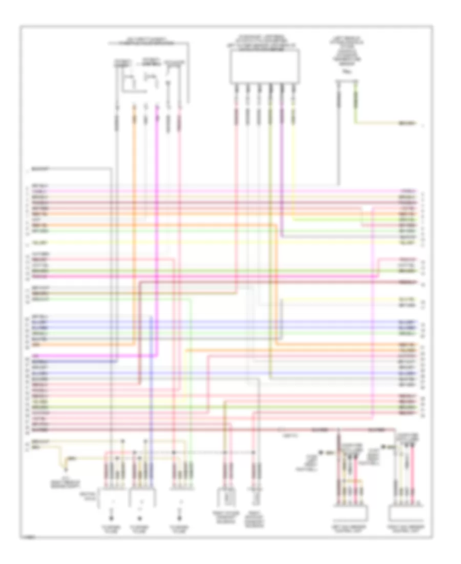
3.5L, Engine Performance Wiring Diagram (1 of 6) for Mercedes-Benz SLK350 2014
List of elements for 3.5L, Engine Performance Wiring Diagram (1 of 6) for Mercedes-Benz SLK350 2014:
- +5v
- A-p-msvh1
- A-p-msvl1
- A-s-hfm
- A-s-su2
- A-t-agr2m
- A-t-agr2p
- A-t-kwtv
- C4i
- C6i
- C9g
- Coolant thermostat heating element
- Cylinder 5 fuel injector
- Dcm
- Dcp
- E-a-dskhp1
- E-a-tans
- E-f-agrm
- E-f-agrp2
- Engine oil pump valve
- Ev1
- Ev2
- Ev3
- Ev4
- Ev5
- Front sam control unit w/ fuse & relay module (left rear of engine compt)
- Fuse 10a
- Fuse 7.5a
- Hot at all times
- Hot w/ chassis circuit 87 relay energized
- Hot w/ circuit 15 relay energized
- Imp
- Intake manifold resonance flap switch over valve
- Intake manifold selector drum switch over valve
- Ip1s
- Ip2s
- Left o2 sensor downstream of catalytic converter (in exhaust, downstream of catalytic converter)
- Ls2hk
- Lsh1hk
- Lshk
- Me-sfi (me) control unit (left side of engine)
- Nca
- Nwsa1
- Nwsa2
- Nwse1
- Nwse2
- Pnk
- Right o2 sensor downstream of catalytic converter (in exhaust, downstream of catalytic converter)
- Right quantity control valve
- X25/2-c2
- Zu 3
- Zu 4
- Zu 5
- Zu 6
- Zue 1
- Zue 6
- Zue2
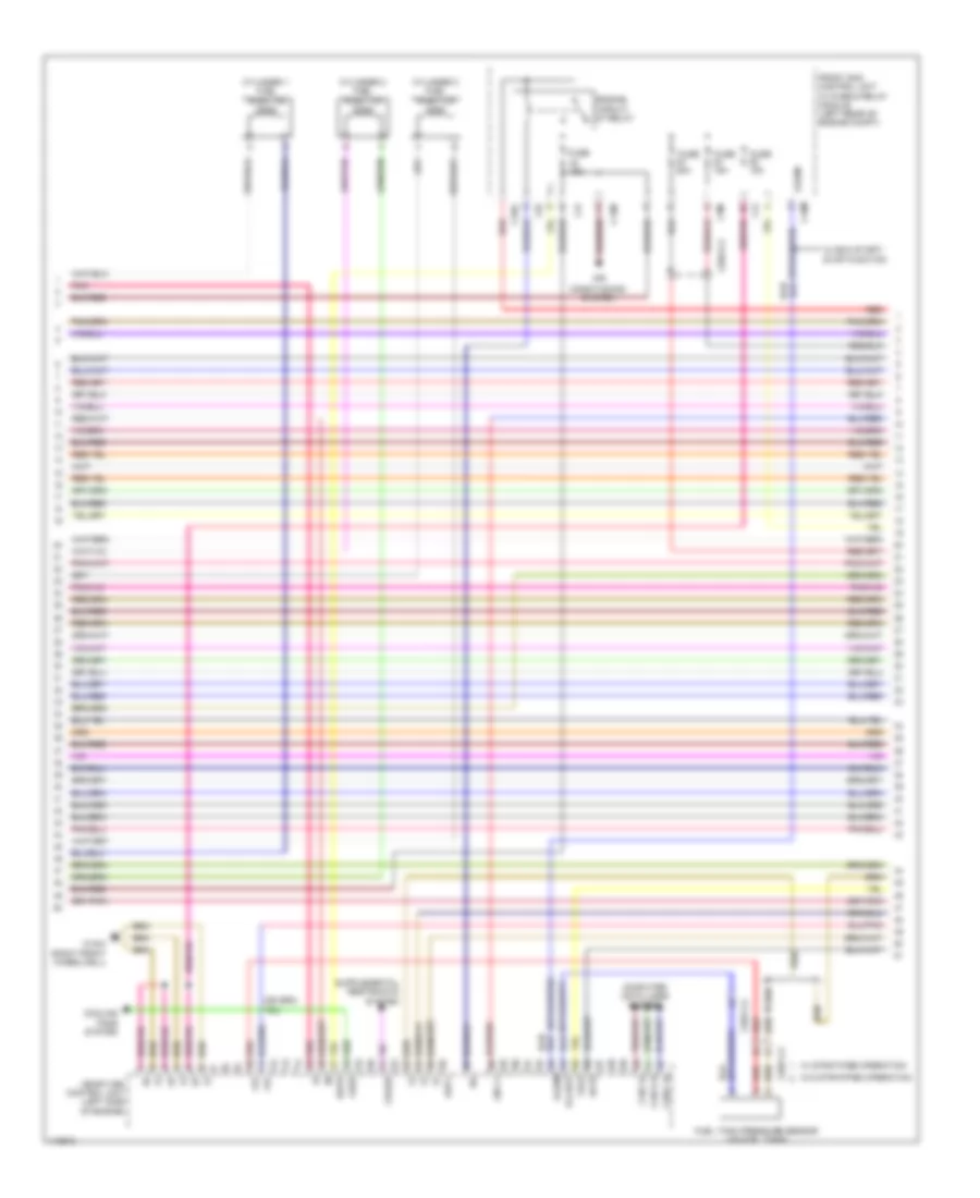
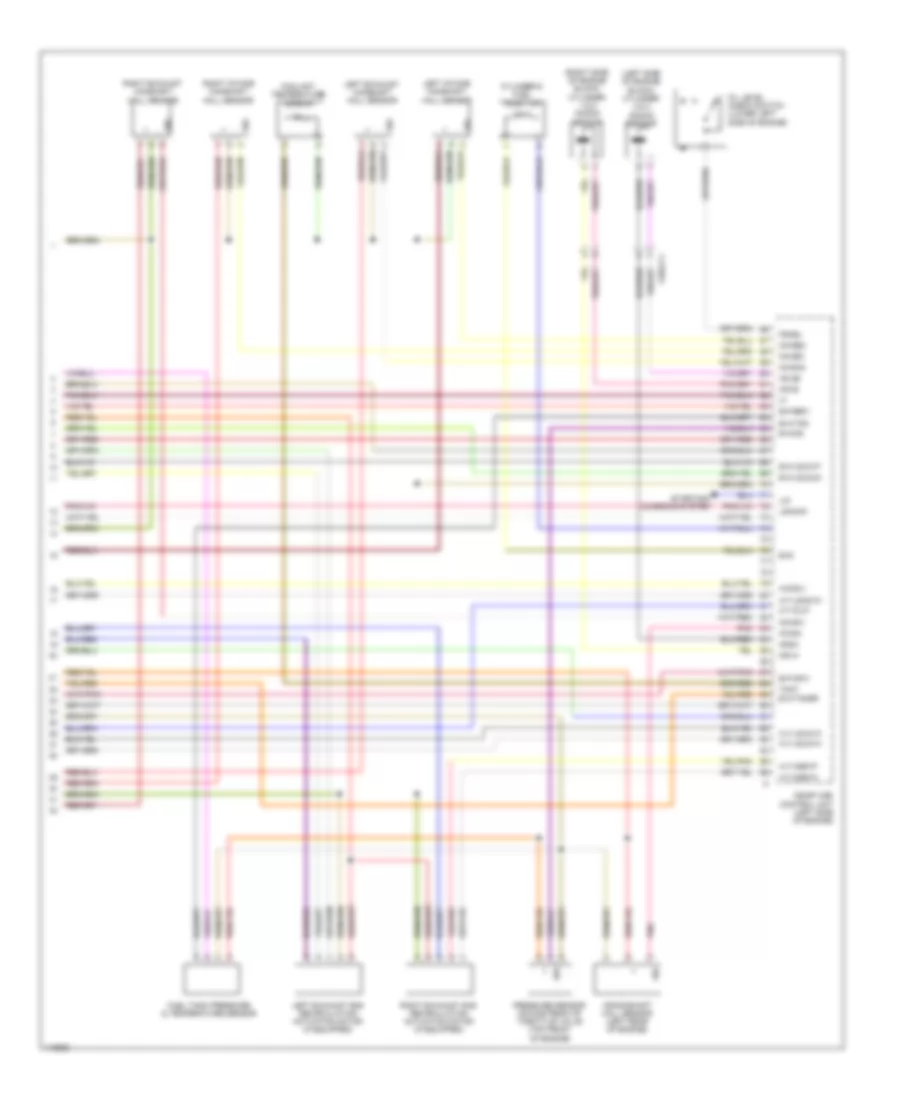
3.5L, Engine Performance Wiring Diagram (2 of 6) for Mercedes-Benz SLK350 2014
List of elements for 3.5L, Engine Performance Wiring Diagram (2 of 6) for Mercedes-Benz SLK350 2014:
- +5v
- Air
- C14m
- C16s
- C18m
- C3m
- C4i
- C6i
- Can c h
- Can e h
- Can i h
- Computer data lines system
- Conditioning system
- Cooling fans system
- Crash
- Cylinder 1 fuel injector
- Cylinder 2 fuel injector
- Cylinder 3 fuel injector
- E-a-dst
- Ekpr
- Engine circuit 87 relay
- Front sam control unit w/ fuse & relay module (left rear of engine compt)
- Fuel tank pressure sensor (on fuel tank)
- Fuse 15a
- Fuse 20a
- Kup1
- Lin c1
- Lues
- Me-sfi (me) control unit (left side of engine)
- Pnk
- Red
- S-sam
- Sp1s
- Tag2
- W/ eco start/ stop function
- W/ stratified operation
- W/o stratified operation
- W16/4 (right front wheelwell)
- X25/2-c2
- X25/7-c2
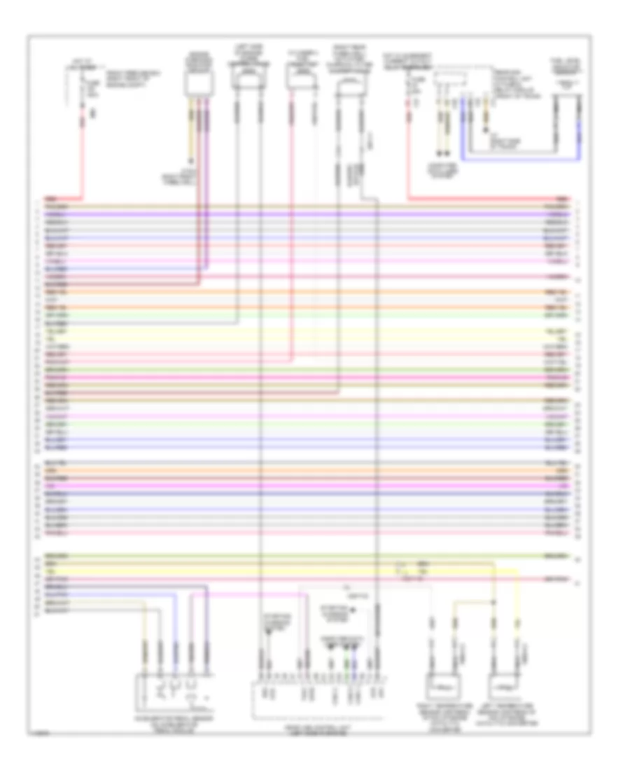
3.5L, Engine Performance Wiring Diagram (3 of 6) for Mercedes-Benz SLK350 2014
List of elements for 3.5L, Engine Performance Wiring Diagram (3 of 6) for Mercedes-Benz SLK350 2014:
- (left side of engine) purge control valve
- (right rear wheelwell) activated charcoal filter shutoff valve
- 25/7-c1
- Aav
- Accelerator pedal sensor (on accelerator pedal module)
- C3i
- C5h
- C7i
- C9i
- Can c l
- Can e l
- Can i l
- Computer data lines system
- Cylinder 4 fuel injector
- Engine diagnosis radiator sensor
- Front prefuse box (right front of engine compt)
- Fuel level indicator sensor
- Fuse 150a
- Fuse 25a
- Hot at all times
- Hot w/ quiescent current cutout relay energized
- Left temperature sensor upstream of nox storage catalytic converter
- Me-sfi (me) control unit (left side of engine)
- Mr2
- Nca
- Rear sam control unit w/ fuse & relay module (front of trunk)
- Red
- Reg
- Right temperature sensor upstream of nox storage catalytic converter
- Sp2s
- Starting/ charging system
- Str
- Str-
- Tag1
- W16/4 (right front wheelwell)
- W7 (right side of trunk)
- X25/7-c2
- X86/3-c2
- X86/4-c2
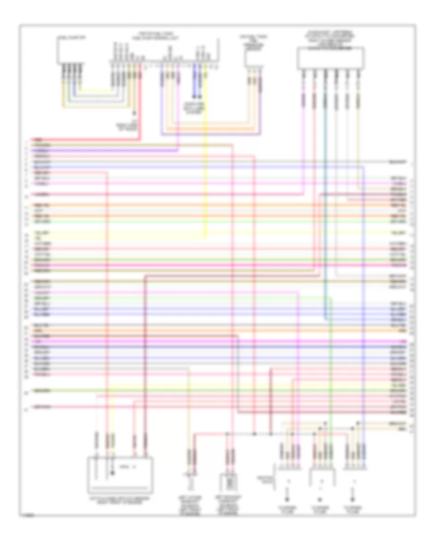
3.5L, Engine Performance Wiring Diagram (4 of 6) for Mercedes-Benz SLK350 2014
List of elements for 3.5L, Engine Performance Wiring Diagram (4 of 6) for Mercedes-Benz SLK350 2014:
- (+)
- (-)
- (in exhaust, upstream of catalytic converter) right oxygen sensor upstream of catalytic converter
- (on fuel tank) fuel pressure sensor
- (top of fuel tank) fuel pump control unit
- Can c h
- Can c l
- Computer data lines system
- Ekp
- Ekp-ec-u
- Ekp-ec-v
- Ekp-ec-w
- Fuel pump (fp)
- Gnd
- Hot film mass air flow sensor (right front of engine)
- Ignition coils
- Kds sig
- Left exhaust camshaft solenoid (left front of engine)
- Left intake camshaft solenoid (left front of engine)
- Nca
- Red
- To spark plugs
- W7 (right side of trunk)
3.5L, Engine Performance Wiring Diagram (5 of 6) for Mercedes-Benz SLK350 2014
List of elements for 3.5L, Engine Performance Wiring Diagram (5 of 6) for Mercedes-Benz SLK350 2014:
- (in exhaust, upstream of catalytic converter) left oxygen sensor upstream of catalytic converter
- (left rear of intake manifold) intake manifold intake air temperature sensor
- (on throttle body) throttle valve actuator
- Actuator motor
- Computer data lines system
- Ignition coils
- Left nox sensor control unit
- Nca
- Pnk
- Potenti- ometer 1
- Potenti- ometer 2
- Right exhaust camshaft solenoid
- Right intake camshaft solenoid
- Right nox sensor control unit
- To spark plugs
- W11 (right rear of engine compt)
- W15/5 (left front footwell)
- W15/7 (right front footwell)
- X25/7-c1
- X86/3-c1
- X86/4-c1
3.5L, Engine Performance Wiring Diagram (6 of 6) for Mercedes-Benz SLK350 2014
List of elements for 3.5L, Engine Performance Wiring Diagram (6 of 6) for Mercedes-Benz SLK350 2014:
- (left side of engine block) cylinder 3 & 4 knock sensor
- (right side of engine block) cylinder 1 & 2 knock sensor
- A-s-sui
- A-t-agr1n
- A-t-agr1p
- A-t-lsh2vk
- A-t-oilp
- A-v-lsu2va
- A-v-lsu2vm
- Coolant temperature sensor
- Crankshaft hall sensor (left rear of engine)
- Cylinder 6 fuel injector
- E-a-ds
- E-a-lsu21p
- E-a-lsu2un
- E-a-tansr
- E-a-tks
- E-f-hfm1
- E-f-ref1
- Ev6
- Fsoel
- Fuel tank pressure & temperature sensor
- Ks 2b
- Ks1a
- Ks1b
- Ks2a
- Kwga
- Left exhaust camshaft hall sensor
- Left exhaust gas recirculation actuation motor (if equipped)
- Left intake camshaft hall sensor
- Lin
- Lsh2hk
- Me-sfi (me) control unit (left side of engine)
- Nwga1
- Nwga2
- Nwge1
- Nwge2
- Oil level check switch (lower left side of engine)
- Pnk
- Pressure sensor downstream of throttle valve (top front of engine)
- Right exhaust camshaft hall sensor
- Right exhaust gas recirculation actuation motor (if equipped)
- Right intake camshaft hall sensor
- Sig
- Starting/ charging system
- Tmot
- X25/2-c1

 Čeština
 Dansk
Dansk Deutsch
 English
 English
 Español
 Suomi
Suomi Français
 Français
 עברית
עברית Hrvatski
 Magyar
 Italiano
 日本語
日本語 한국어
한국어 Nederlands
 Polski
 Português
 Português
 Română
 Русский
 Slovenčina
 Slovenščina
 Svenska
 Türkçe
 中文 (中国)