
 Čeština
 Dansk
Dansk Deutsch
 English
 English
 Español
 Suomi
Suomi Français
 Français
 עברית
עברית Hrvatski
 Magyar
 Italiano
 日本語
日本語 한국어
한국어 Nederlands
 Polski
 Português
 Português
 Română
 Русский
 Slovenčina
 Slovenščina
 Svenska
 Türkçe
 中文 (中国)

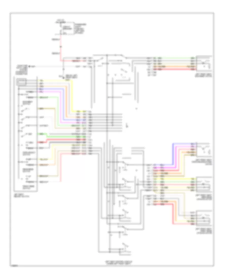
MEMORY SYSTEMS
Memory System Wiring Diagrams for Volvo V90 1998
List of elements for Memory System Wiring Diagrams for Volvo V90 1998:

AIR CONDITIONINGANTI-LOCK BRAKESENGINE PERFORMANCEHEADLIGHTSDEFOGGERSHORNEXTERIOR LIGHTSMEMORY SYSTEMSGROUND DISTRIBUTIONINTERIOR LIGHTSPOWER ANTENNAPOWER MIRRORSINSTRUMENT CLUSTERPOWER DISTRIBUTIONPOWER DOOR LOCKSSHIFT INTERLOCKSRADIOSTARTING/CHARGINGWARNING SYSTEMSTRANSMISSIONSUPPLEMENTAL RESTRAINTSPOWER WINDOWSWIPER/WASHERANTI-THEFTCOOLING FANCRUISE CONTROLCOMPUTER DATA LINESPOWER SEATSPOWER TOP/SUNROOF