Čeština
 Dansk
Dansk Deutsch
 English
 English
 Español
 Suomi
Suomi Français
 Français
 עברית
עברית Hrvatski
 Magyar
 Italiano
 日本語
日本語 한국어
한국어 Nederlands
 Polski
 Português
 Português
 Română
 Русский
 Slovenčina
 Slovenščina
 Svenska
 Türkçe
 中文 (中国)

NAVIGATION
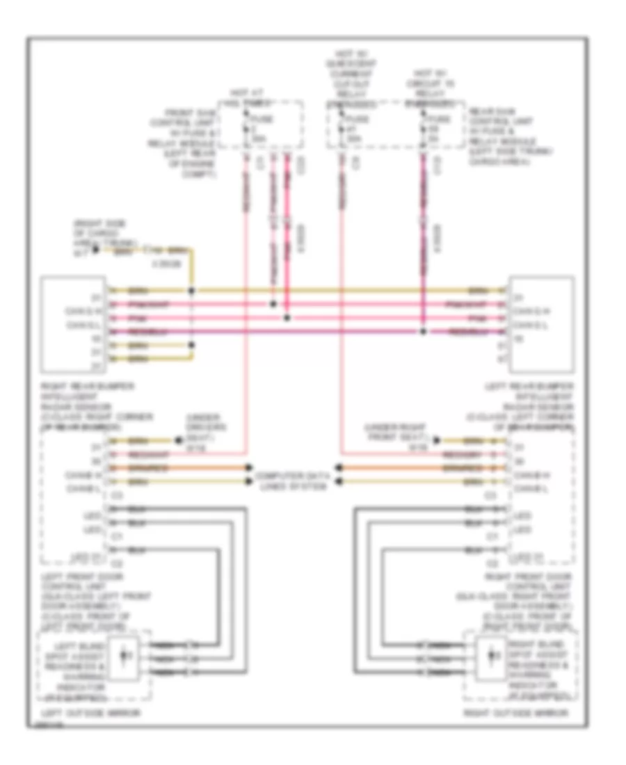
Blind Spot Information System Wiring Diagram for Mercedes-Benz C250 2012
List of elements for Blind Spot Information System Wiring Diagram for Mercedes-Benz C250 2012:

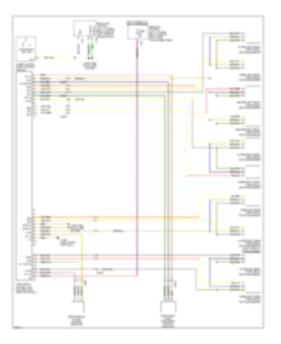
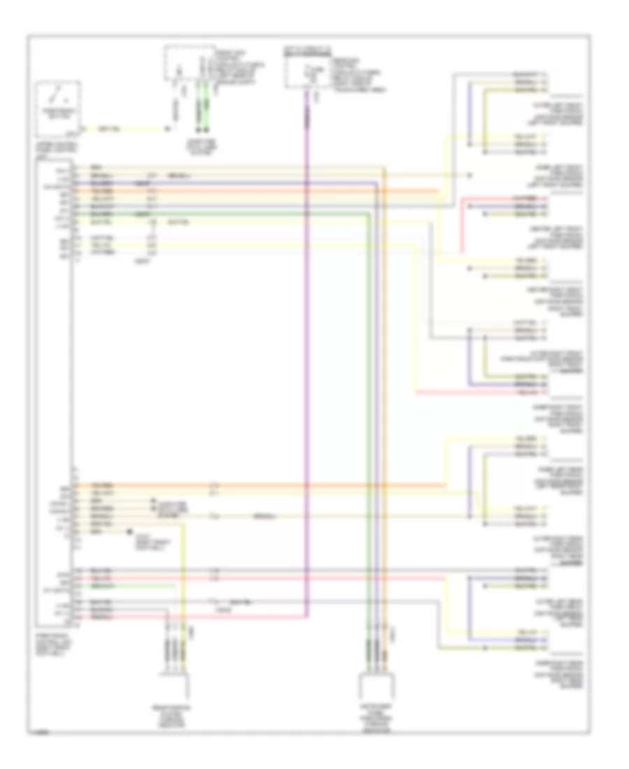
COMAND Actuation Wiring Diagram (1 of 3) for Mercedes-Benz C250 2012
List of elements for COMAND Actuation Wiring Diagram (1 of 3) for Mercedes-Benz C250 2012:
COMAND Actuation Wiring Diagram (2 of 3) for Mercedes-Benz C250 2012
List of elements for COMAND Actuation Wiring Diagram (2 of 3) for Mercedes-Benz C250 2012:

COMAND Actuation Wiring Diagram (3 of 3) for Mercedes-Benz C250 2012
List of elements for COMAND Actuation Wiring Diagram (3 of 3) for Mercedes-Benz C250 2012:
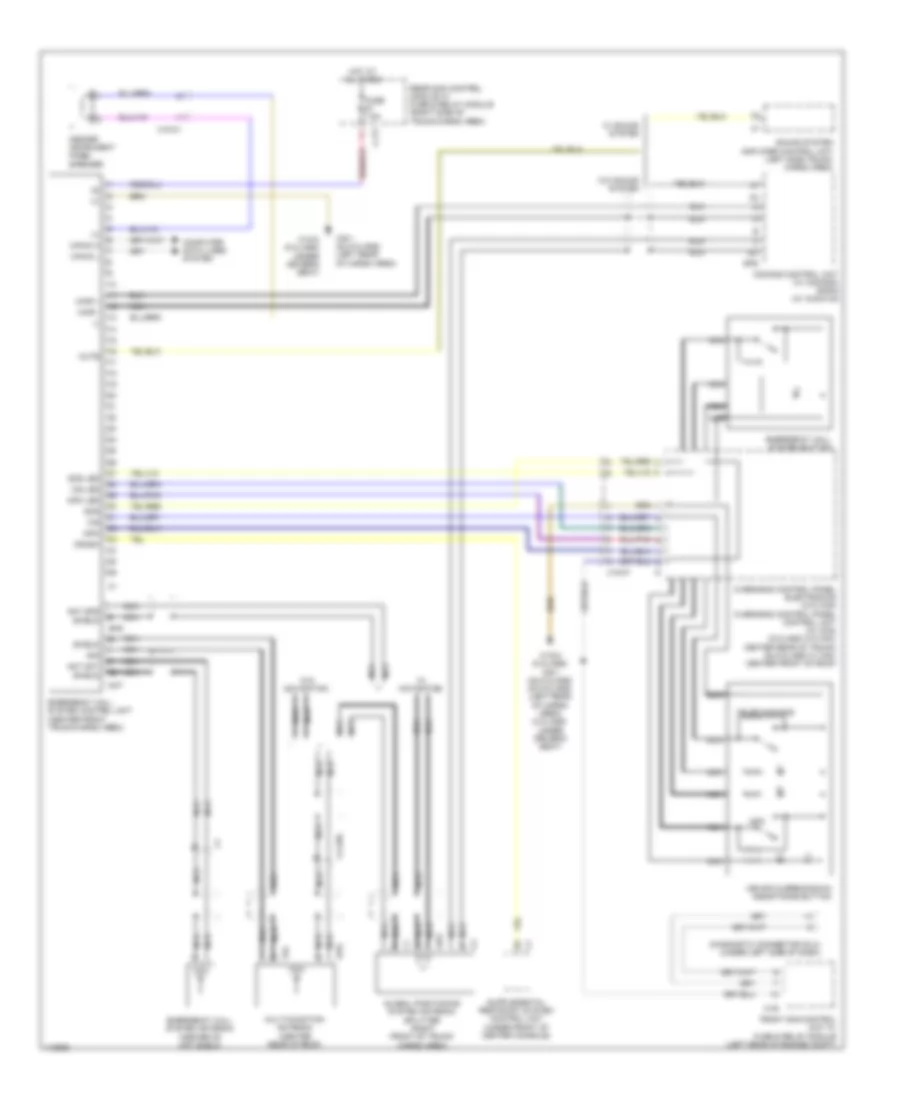
Emergency Call Wiring Diagram for Mercedes-Benz C250 2012
List of elements for Emergency Call Wiring Diagram for Mercedes-Benz C250 2012:
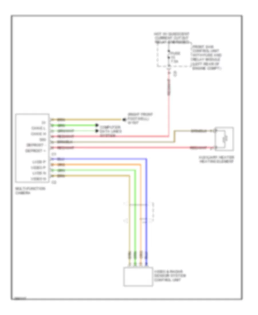
Multifunction Camera Wiring Diagram for Mercedes-Benz C250 2012
List of elements for Multifunction Camera Wiring Diagram for Mercedes-Benz C250 2012:
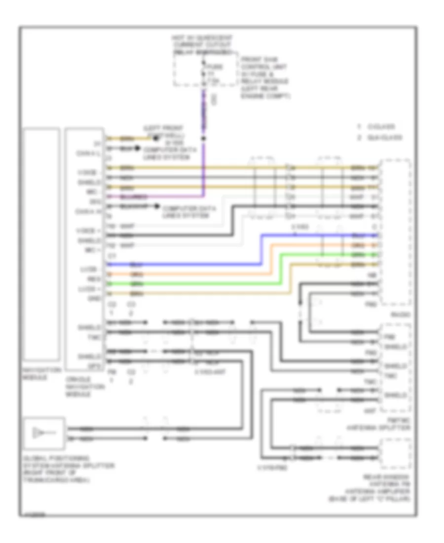
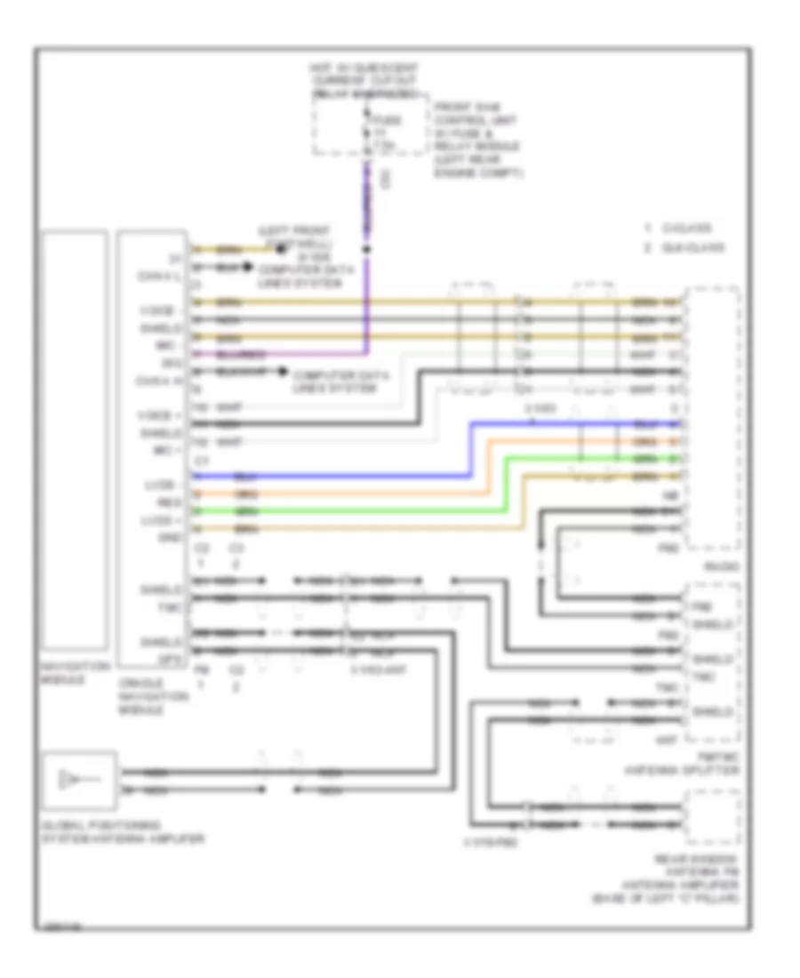
Navigation Wiring Diagram for Mercedes-Benz C250 2012
List of elements for Navigation Wiring Diagram for Mercedes-Benz C250 2012:
Parktronic Wiring Diagram for Mercedes-Benz C250 2012
List of elements for Parktronic Wiring Diagram for Mercedes-Benz C250 2012: