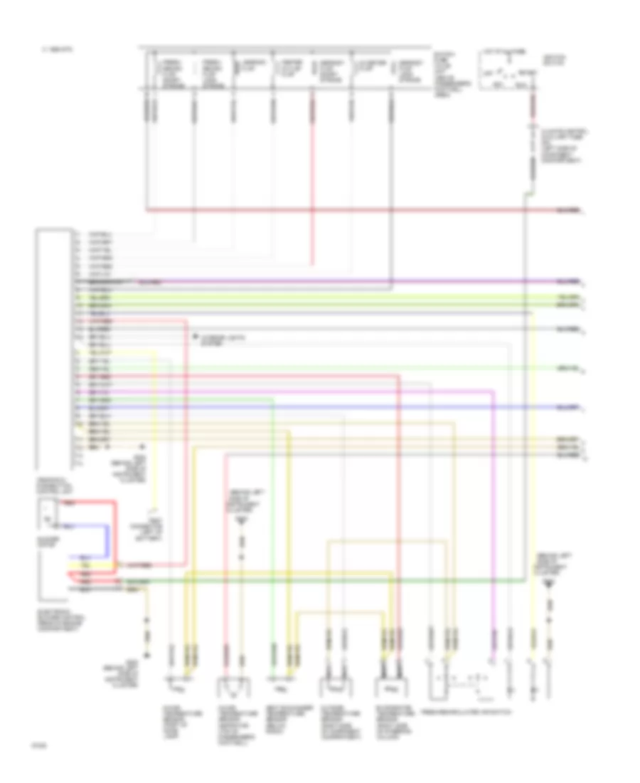
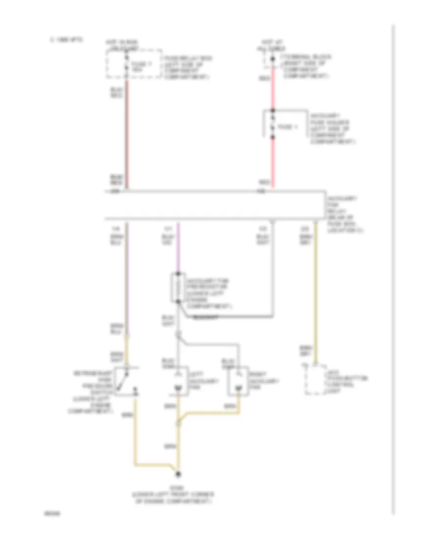
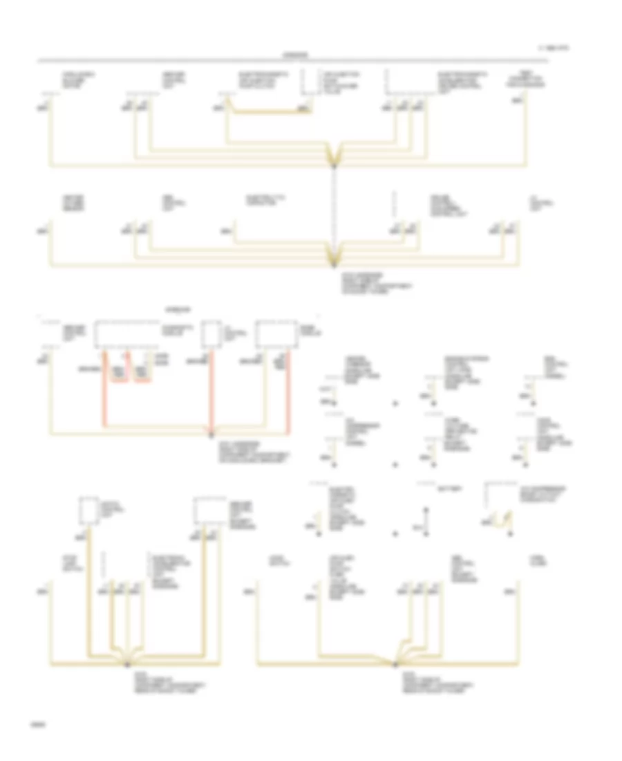
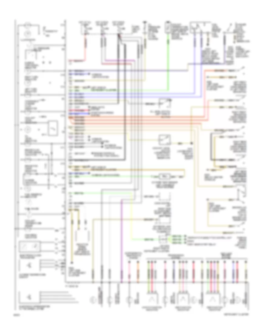
AIR CONDITIONING
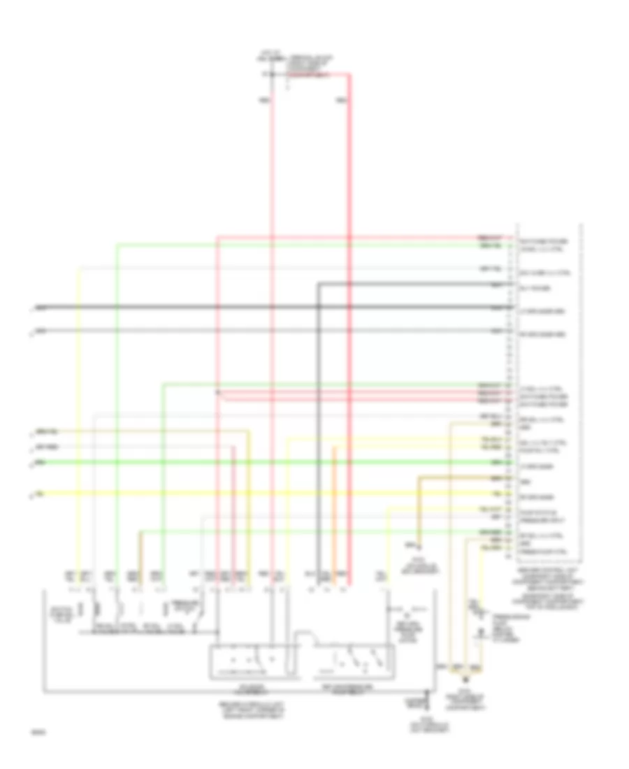
Air Conditioning Wiring Diagrams (1 of 2) for Mercedes-Benz 500E 1993
List of elements for Air Conditioning Wiring Diagrams (1 of 2) for Mercedes-Benz 500E 1993:
- (behind left
- (right side of steering column)
- Acc
- Blower motor
- C 1995 vftc
- Center outlet flap
- Climate control auxiliary fuse 30a (left side of component compartment)
- Cluster)
- Defrost flap long stroke
- Defrost flap short stroke
- Diverter flap
- Electronic blower control (rear of engine compartment)
- Evaporator temperature sensor
- Fresh/ recirc flap long stroke
- Fresh/ recirc flap short stroke
- Fresh/recirculated air switch
- G202
- G202 (behind left side of instrument cluster)
- Heat exchanger temperature sensor (below radio)
- Hot at all times
- Ignition switch
- In-car temperature sensor (part of dome lamp)
- In-car temperature sensor aspirator (top of passenger's footwell)
- Instrument
- Interior lights system
- Legroom flap
- Nca
- Off
- Outside temperature sensor (right side of component compartment)
- Red
- Run
- Side of
- Start
- Switch- over valve unit (above passenger's footwell area)
- Tempmatic pushbutton control unit
- Test connector (left of battery)
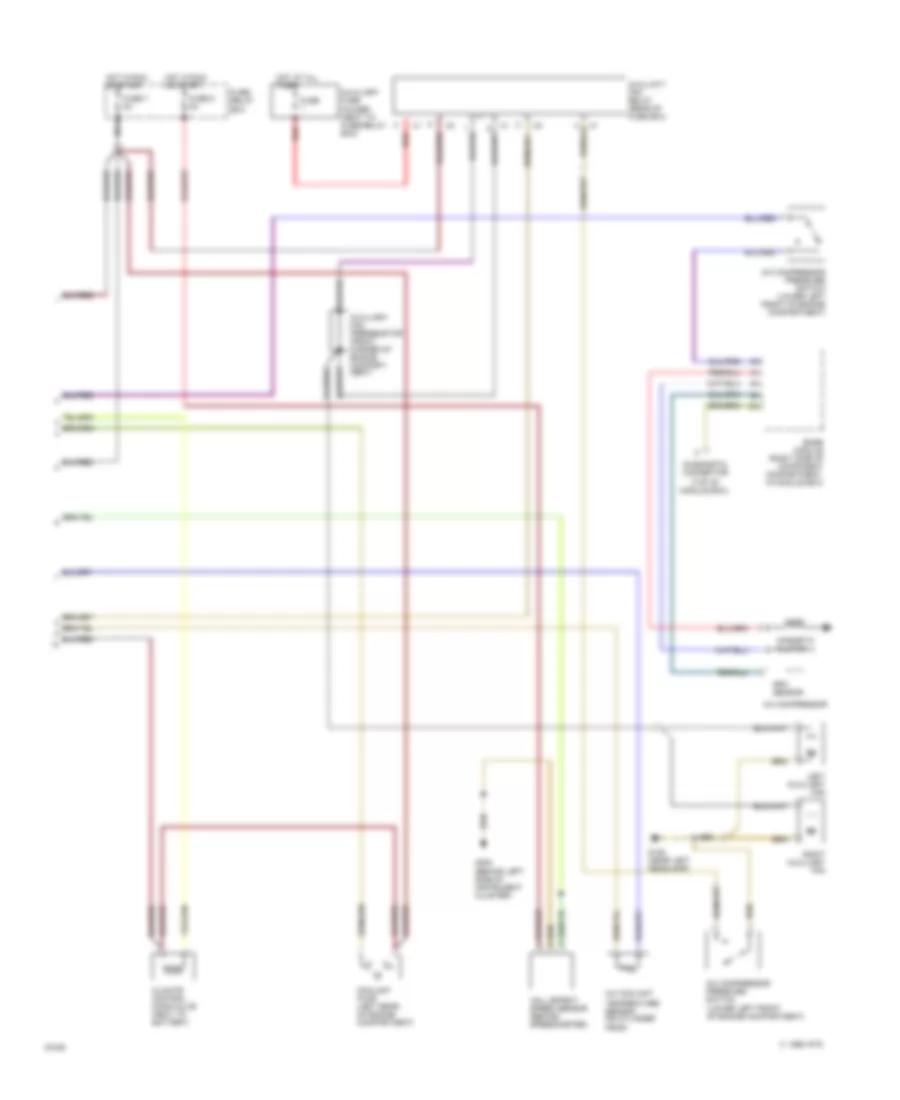
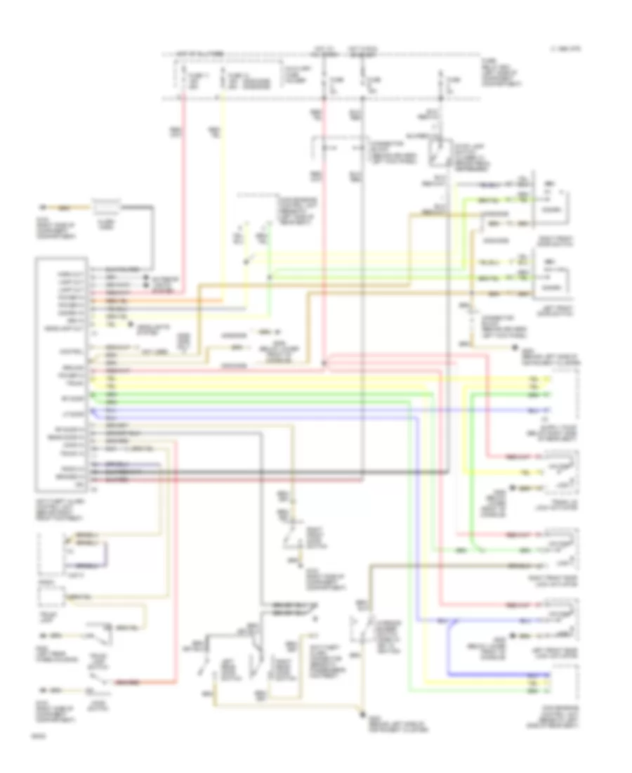
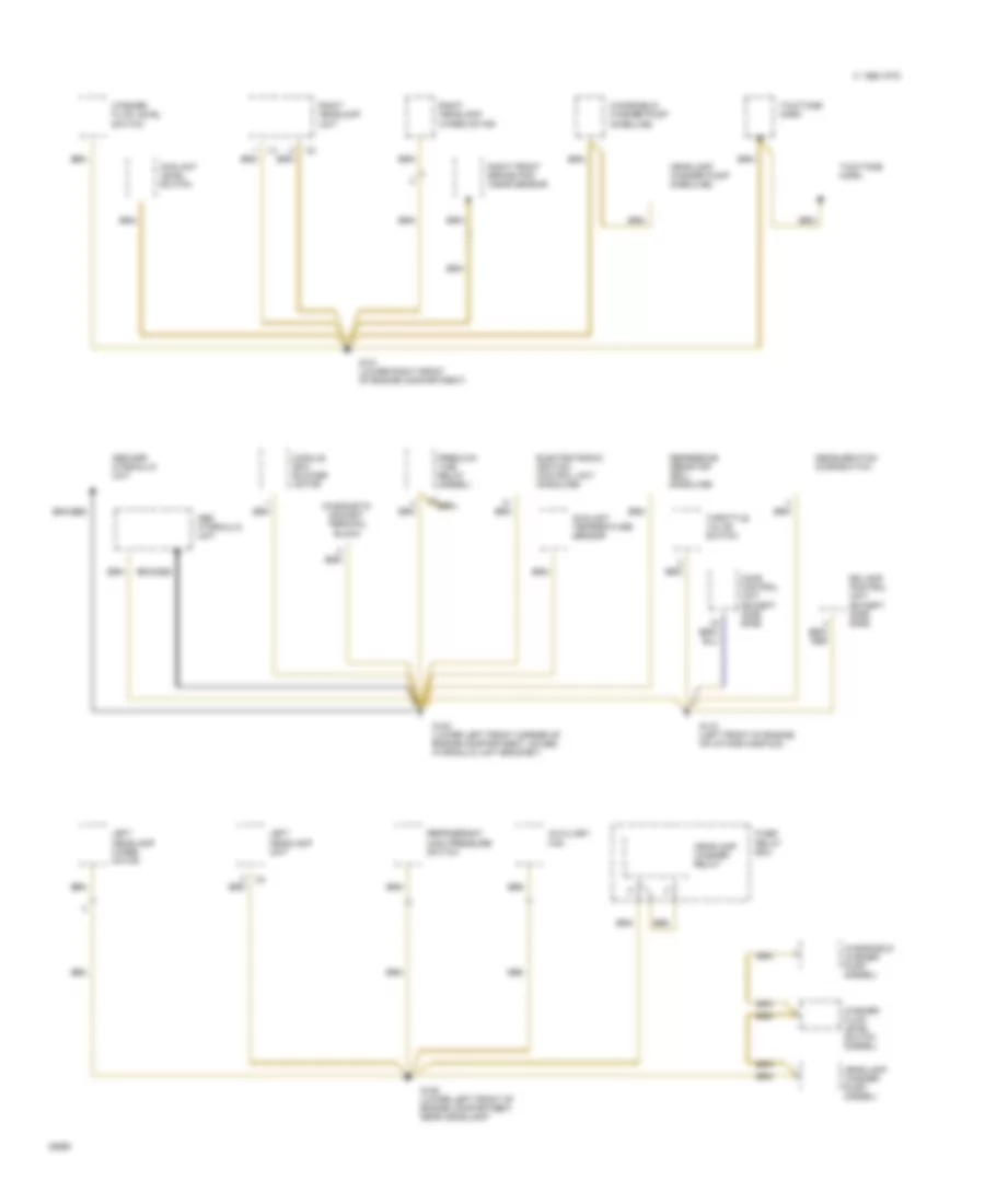
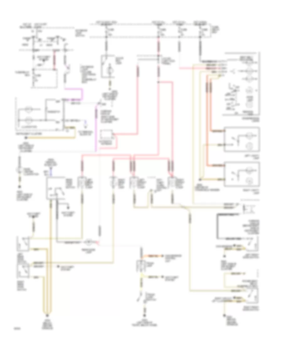
Air Conditioning Wiring Diagrams (2 of 2) for Mercedes-Benz 500E 1993
List of elements for Air Conditioning Wiring Diagrams (2 of 2) for Mercedes-Benz 500E 1993:
- (lower left front of engine compartment)
- (top of
- A/c compressor
- A/c compressor pressure switch
- A/c compressor pressure switch (lower left front of engine compartment)
- A/c coolant
- Auxiliary fan preresistor (front corner of engine compart- ment)
- Auxiliary fuse holder (next to fuse/relay box)
- Auxiliaty fan relay (rear of fuse box)
- Base module (right side of component compartment, in module box)
- C 1995 vftc
- Climate control monovalve (next to battery)
- Coolant pump (left rear of engine compartment)
- Diagnostic connector
- Fuse
- Fuse 5 8a
- Fuse 7 8a
- Fuse/ relay box
- G106 (near left headlamp)
- G202 (behind left side of instrument cluster)
- Hall effect speed sensor (behind speedometer)
- Hot at all times
- Hot in run or start
- Left auxiliary fan
- Magnetic clutch
- Module box)
- Nca
- Red
- Right auxiliary fan
- Rpm sensor
- Temperature sensor (on cylinder head)
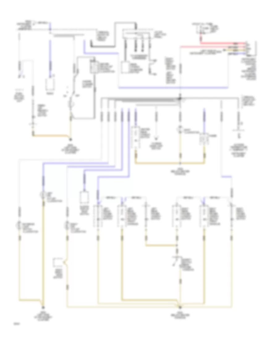
ANTI-LOCK BRAKES
Anti-Lock Brakes Wiring Diagram for Mercedes-Benz 500E 1993
List of elements for Anti-Lock Brakes Wiring Diagram for Mercedes-Benz 500E 1993:
- (400e-right side
- (500e-right side
- (left front corner of engine compartment)
- (on hydraulic unit bracket)
- (on intake manifold)
- (right side of
- 87e
- Abs control unit
- Abs hydraulic unit
- Abs ind. ctrl
- Abs warning ind.
- Base module
- Behind battery)
- Braid
- Brake light sw
- Charging system
- Compartment)
- Compartment,
- Compartment, top
- Component
- Computer data lines system
- Copper
- Cruise control switch
- Cruise/idle speed control module
- Diagnostics
- Differential rear speed sensor
- Engine running sig
- Exterior lamp failure monitoring unit
- Fuse 5 8a
- Fuse 6 8a
- Fuse/ relay box (left side of component compartment)
- G100
- G103
- G131
- Grd
- Ground
- Hot at all times
- Hot in run or start
- In module box)
- Instrument cluster
- Left front wheel speed sensor
- Left of battery)
- Lf sol valve
- Lf spd snsr
- Lf spd snsr grd
- Lf vlv ctrl
- Nca
- Of component
- Of component compartment,
- Of module box)
- Pnk
- Pnk/ red
- Power input
- Pump motor relay
- Pump on input
- Pump rly ctrl
- Rear axle sol valve
- Rear spd snsr
- Red
- Return pump
- Rf sol valve
- Rf spd snsr
- Rf spd snsr grd
- Rf vlv ctrl
- Right front wheel speed sensor
- Rly power
- Rr axle vlv ctrl
- Rr spd snsr grd
- Sol vlv rly ctrl
- Solenoid valve relay
- Stop light switch (top of brake pedal support)
- Terminal block (right side of component compartment)
- Test connection for diagnosis
- Throttle position
- Throttle reduction
- Twisted pair
- Twisted pairs
- Vlv relay status
Traction Control Wiring Diagram (1 of 2) for Mercedes-Benz 500E 1993
List of elements for Traction Control Wiring Diagram (1 of 2) for Mercedes-Benz 500E 1993:
- (400e-right side
- (400e-right side of component compartment, left of battery)
- (500e-right side
- (500e-right side of component compartment, top of module box)
- (on center console)
- (right side of
- 87e
- Abs ind. ctrl
- Abs warning ind.
- Abs/asr control unit
- Asr function ind.
- Asr function indicator
- Asr ind. ctrl
- Asr warning ind.
- Base module
- Behind battery)
- Brake fluid level switch (on master cylinder)
- Brake ind.
- Charging system
- Compartment,
- Compartment, top
- Component
- Computer data lines system
- Cruise control switch
- Cruise/idle speed control module
- Diagnostics
- Engine running sig
- Exterior lamp failure monitoring unit
- Exterior lamp switch
- Fuse 5 8a
- Fuse 6 8a
- Fuse 7 16a
- Fuse/ relay box (left side of component compartment)
- G200 (left kick panel)
- Hot in run or start
- In module box)
- Instrument cluster
- Left front wheel speed sensor
- Left rear wheel speed sensor
- Lf sol vlv
- Lr spd snsr
- Lr spd snsr grd
- Nca
- Normal ind.
- Of component
- Of component compartment,
- Of module box)
- Park brake switch (at park brake release)
- Pnk/ red
- Power
- Rheostat
- Right front wheel speed sensor
- Right rear wheel speed sensor
- Rr spd snsr
- Rr spd snsr grd
- Separation diode
- Snow chain ind.
- Snow chain logic switch
- Stop light input
- Stop light switch (top of brake pedal support)
- Test connection for diagnosis
- Throttle position
- Throttle reduction
Traction Control Wiring Diagram (2 of 2) for Mercedes-Benz 500E 1993
List of elements for Traction Control Wiring Diagram (2 of 2) for Mercedes-Benz 500E 1993:
- (500e-right side of component compartment,
- (left front corner of engine compartment)
- (on hydraulic unit bracket)
- (on module
- (right side of
- Abs/asr control unit (400e-right side of component compartment,
- Abs/asr hydraulic unit
- Behind battery)
- Box bracket)
- Compartment)
- Component
- Copper braid
- Cylinder)
- G100
- G103
- Grd
- Hot at all times
- Lf sol valve
- Lf sol vlv ctrl
- Lf spd snsr
- Lf spd snsr grd
- Lr sol valve
- Lr sol vlv ctrl
- Nca
- Press pump ctrl
- Pressure input
- Pressure switch
- Pressurizing
- Pump (below master
- Pump relay
- Pump rly ctrl
- Pump status
- Red
- Return/ pressure pump motor
- Return/pressure
- Rf sol valve
- Rf sol vlv ctrl
- Rf spd snsr
- Rf spd snsr grd
- Rly power
- Rr sol valve
- Rr sol vlv ctrl
- Sol vlv rly ctrl
- Solenoid
- Sw/ over vlv ctrl
- Switch- over sol valve
- Switched power
- Terminal block (right side of component compartment)
- Top of module box)
- Valve relay
ANTI-THEFT
Anti-theft Wiring Diagram for Mercedes-Benz 500E 1993
List of elements for Anti-theft Wiring Diagram for Mercedes-Benz 500E 1993:
- (300d/300e) (400e/500e)
- 300d/300e
- 400e/ 500e only
- 400e/500e
- Alarm horn
- Anti-theft alarm connector (beneath passenger's footrest)
- Anti-theft alarm control unit (behind right front footrest)
- Arm
- Arm in
- Auxiliary fuse holder
- Brakes in
- C 1995 vftc
- Connector block (behind driver's left kick panel)
- Control
- Convenience control unit (beneath left side of rear seat)
- Disarm
- Disarm in
- Exterior lights system
- Fuse 11 16a 25a
- Fuse 12 16a 25a
- Fuse 8a
- Fuse b 16a
- Fuse c 8a
- Fuse/ relay box (left side of component compartment)
- G103 (right side of component compartment)
- G202 (behind left side of instrument cluster)
- G206 (below lower front of console)
- G402 (left rear wheelhousing)
- Ground
- Headlamp out
- Headlights system
- Hood in
- Hood switch
- Horn out
- Hot at all times
- Hot in run or start
- Ign
- Lamp out
- Left front door lock actuator
- Left front door switch
- Left rear door switch
- Lf door
- Lock
- Not used
- Power in
- Radio
- Radio in
- Rear door in
- Rf door
- Rf door in
- Right front door lock actuator
- Right front door switch
- Right rear door switch
- Stop lamp switch (closed w/ brake pedal depressed)
- Trunk
- Trunk in
- Trunk lamp
- Trunk lamp switch
- Trunk lid lock actuator
- Unlock
- Warning buzzer switch (open w/ key in ignition)
- X42/13
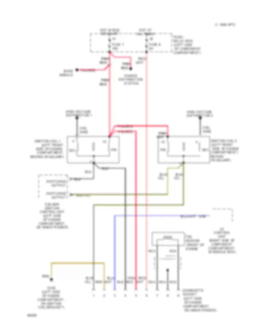
COMPUTER DATA LINES
Diagnostic Socket Wiring Diagram for Mercedes-Benz 500E 1993
List of elements for Diagnostic Socket Wiring Diagram for Mercedes-Benz 500E 1993:
- (front of
- (left front
- (left side
- (left side of engine
- Base module
- Behind
- Behind headlamp)
- C 1995 vftc
- Coil wire
- Compartment,
- Diagnostic socket
- Distribution
- Engine
- Ezl/akr ignition control unit (left side of engine compartment, on inner fender)
- Fuse 7 16a
- Fuse 9 8a
- Fuse/ relay box
- G102 (left side of engine compartment, on ignition coil bracket)
- Headlamp)
- High voltage distributor 1
- High voltage distributor 2
- Hot at all times
- Hot in run or start
- Ignition coil 1
- Ignition coil 2
- Lh control unit (right side of component compartment, in module box)
- Nca
- Of component compartment)
- On inner fender)
- Pnk/
- Pnk/ pnk/
- Pnk/red
- Power
- Pri
- Red
- Red red
- Red/
- Sec
- Side of engine compartment)
- Side of engine compartment,
- Switching output
- System
- Tdc sensor
Test Connector Wiring Diagram for Mercedes-Benz 500E 1993
List of elements for Test Connector Wiring Diagram for Mercedes-Benz 500E 1993:
- (400e-right side
- (500e-right side
- (mil)
- * **
- 1/13
- 1st gear start relay (fuse/relay box, position g)
- 400e
- 400e only
- A/5
- A/7
- Abs/asr control unit
- Acc push-button
- Base module (right side of component compartment, in module box)
- Behind battery)
- C 1995 vftc
- California only
- Check engine warning lamp
- Compartment, top
- Control unit
- Controls
- Diagnogstic module (right front footwell)
- Diagnostic module test connection (right side of component compartment, forward of module box)
- Electronic accelerator/ cruise control unit
- Engine
- Engine controls system
- Ezl/akr ignition control unit (left side of engine compartment, on fender)
- G103 (right side of component compartment)
- Instrument cluster
- Left of battery)
- Lh control unit (right side of component compartment, in module box)
- Nca
- Of component
- Of component compartment,
- Of module box)
- Red
- Red/
- Shielded
- Srs control unit (top of transmission tunnel, behind front console)
- System
- Test connection for diagnosis (38-pin)
- W/ asr
- W/o asr * **
- Wires
COOLING FAN
Cooling Fan Wiring Diagram for Mercedes-Benz 500E 1993
List of elements for Cooling Fan Wiring Diagram for Mercedes-Benz 500E 1993:
- (lower left
- (lower left engine compartment)
- (lower left front corner
- 1/1
- 1/2
- 1/4
- 1/5
- 1995 vftc c
- 2/2
- 2/5
- Acc push-button control unit
- All times
- Auxiliary fan preresistor
- Auxiliary fan relay (rear of fuse box, location c)
- Auxiliary fuse holder (left side of component compartment)
- Compartment)
- Engine
- Fuse 1
- Fuse 7 16a
- Fuse/relay box (left side of component compartment)
- G106
- High
- Hot at
- Hot in run
- Left auxiliary fan
- Of engine compartment)
- Or start
- Pressure
- Red
- Refrigerant
- Right auxiliary fan
- Switch
- Terminal block (right side of component compartment)
CRUISE CONTROL
Cruise Control Wiring Diagram for Mercedes-Benz 500E 1993
List of elements for Cruise Control Wiring Diagram for Mercedes-Benz 500E 1993:
- Accel/ set
- Back-up lamp switch
- Base module (right side of component compt, in module box)
- C 1995 vftc
- Cruise control actuator (lower left side of engine)
- Cruise control switch
- Cruise control/idle speed control unit (right side of component compt, in module box)
- Decel/ set
- Fuse 5 8a
- Fuse/ relay box (left side of component compartment)
- G103 (right side of component compt, on shock tower)
- Hot in run or start
- Left control unit (right side of component compt, in module box)
- Nca
- Off
- Resume
- Stop light switch (top of brake pedal, on bracket)
- To throttle
Cruise/Idle Speed Control Wiring Diagram for Mercedes-Benz 500E 1993
List of elements for Cruise/Idle Speed Control Wiring Diagram for Mercedes-Benz 500E 1993:
- (component compartment)
- (right rear corner of engine compt) diagnostic connector
- 87 kp
- 87 ug
- Abs system control module (right rear of engine compt)
- Base module (in module box, on right rear of engine compt)
- Brs
- Can h+
- Can l-
- Computer data lines system
- Cruise control switch
- Cruise control/idle speed control actuator (on left side of engine)
- Cruise control/idle speed control module (in module box, on right rear of engine compt)
- Df ha
- Df vl
- Dfa ha
- Dfa vl
- Exterior lights system
- Fuse 8a
- Fuse and relay box (on left rear corner of engine compt)
- Hot in run or start
- Ip+
- Ip-
- Ips
- Klsk
- Ksk
- Llk
- Lsk
- Nca
- Pnk
- Red
- S+b
- S-b
- Sequential multiport fuel injection control module (right rear of engine compt)
- Sps
- Ssa
- Starter lock-out/ backup lamp switch (on left side of transmission)
- Stop lamp switch (top of brake pedal support)
- Tna
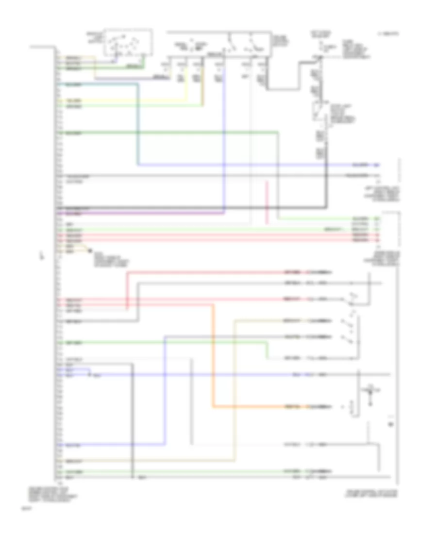
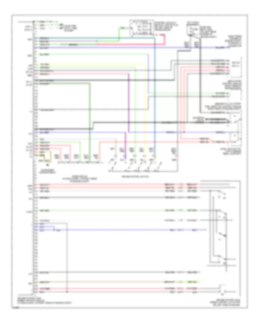
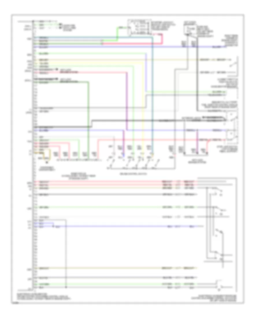
Electronic Accelerator/Cruise/Idle Speed Control Wiring Diagram for Mercedes-Benz 500E 1993
List of elements for Electronic Accelerator/Cruise/Idle Speed Control Wiring Diagram for Mercedes-Benz 500E 1993:
- (component compartment)
- (right rear corner of engine compt) diagnostic connector
- Anti-lock brakes system
- Base module (in module box, on right rear of engine compt)
- Can h+
- Can l-
- Closed throttle position switch (on top of accelerator bracket)
- Computer data lines system
- Cruise control switch
- Dfahl
- Dfavl
- Electronic accelerator/ cruise control/idle speed control module (in module box, on right rear of engine compt)
- Electronic accelerator/cruise control/idle speed control actuator (on left side of engine)
- Exterior lights system
- Fuse 8a
- Fuse and relay box (on left rear corner of engine compt)
- Hot in run or start
- Ips
- Ksk
- Lsk
- M1+
- M1-
- Msk
- Nca
- Pks
- Pnk
- Red
- S+b
- S-b
- Sequential multiport fuel injection control module (right rear of engine compt)
- Sps
- Ssa
- Starter lock-out/ backup lamp switch (on left side of transmission)
- Stop lamp switch (top of brake pedal support)
- Tna
- Upks
- Usk
DEFOGGERS
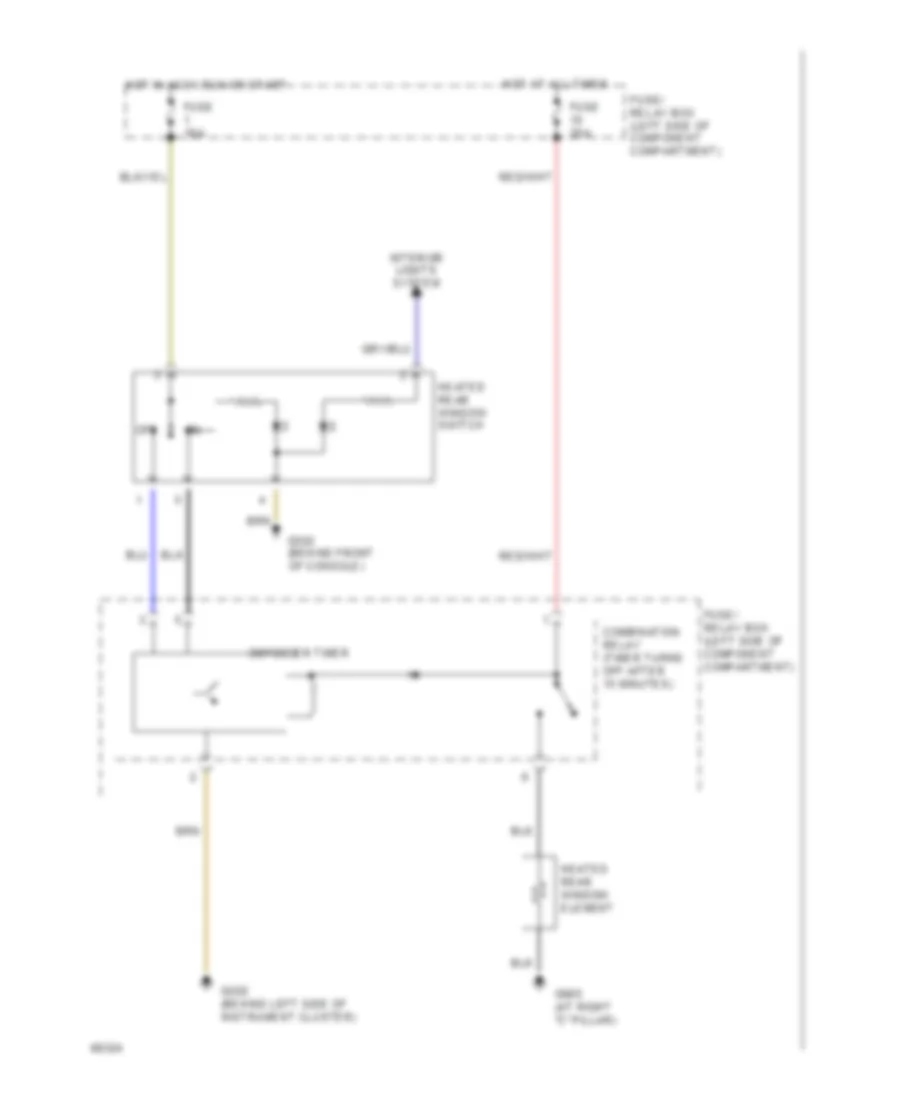
Defogger Wiring Diagram for Mercedes-Benz 500E 1993
List of elements for Defogger Wiring Diagram for Mercedes-Benz 500E 1993:
- Combination relay (timer turns off after 15 minutes)
- Defogger timer
- Fuse 16a
- Fuse 25a
- Fuse/ relay box (left side of component compartment)
- G202 (behind left side of instrument cluster)
- G302 (behind front of console)
- G905 (at right "c" pillar)
- Heated rear window element
- Heated rear window switch
- Hot at all times
- Hot in accy,run or start
- Interior lights system
- Off
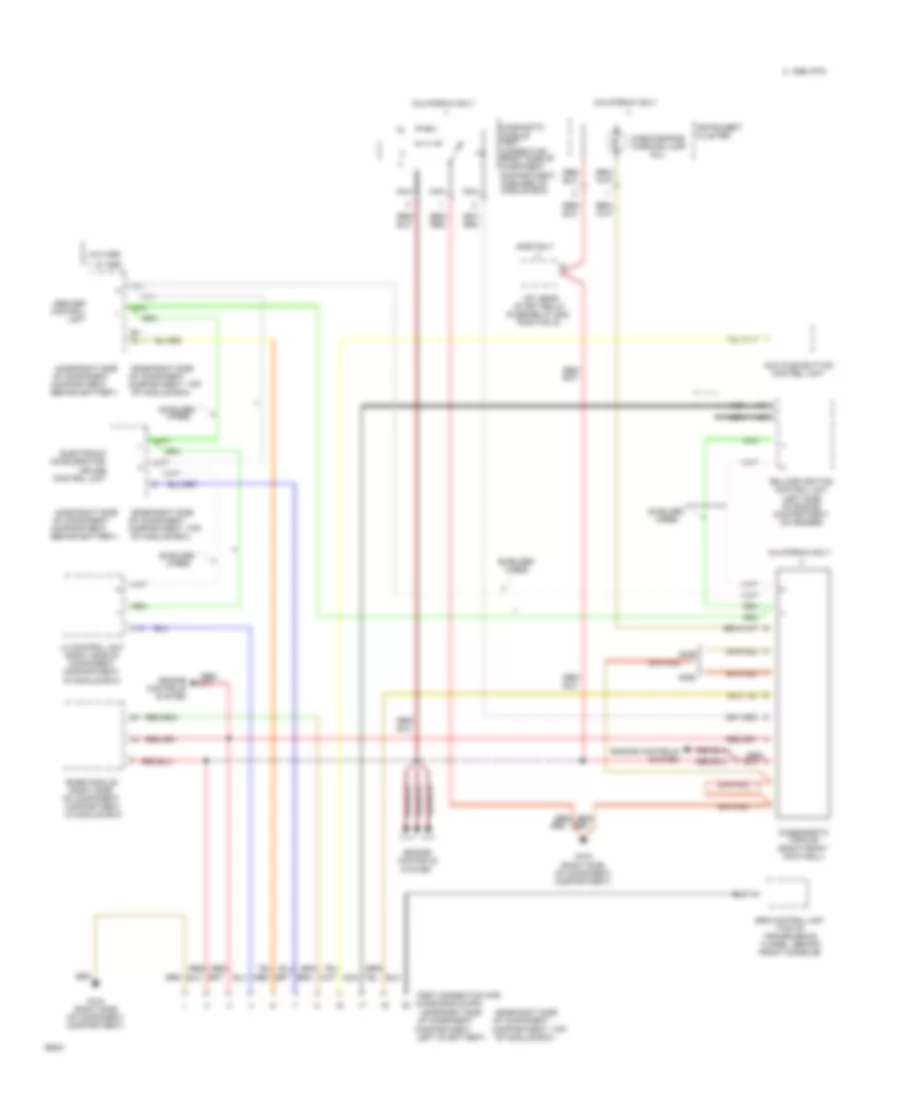
ENGINE PERFORMANCE
5.0L
5.0L, Engine Performance Wiring Diagrams (1 of 2) for Mercedes-Benz 500E 1993
List of elements for 5.0L, Engine Performance Wiring Diagrams (1 of 2) for Mercedes-Benz 500E 1993:
- "b" engagement
- (behind
- (module
- (right
- Abs/ asr control unit
- Accy
- Base module (gm)
- Battery (+)
- Block
- Camshaft position sensor
- Coil wire
- Control
- Crankshaft position sensor
- Ezl/akr ignition control
- Fuel pump
- Fuel pumps relay
- Fuse 8a
- Fuse/ relay box
- G100 (left front wheel well)
- G103 box bracket)
- G103 shock tower)
- G206
- G302 (under console)
- Hmatic/asd stop lamp switch
- Hot at all times
- I/p)
- Idle
- Ignition switch
- Instrument cluster system (tachometer)
- Kickdown switch
- Kickdown valve
- Knock sensor 1 (right)
- Knock sensor 2 (left)
- Lh control unit
- Lh distributor
- Lock
- Nca
- Ohm
- Pnk/red
- Red
- Resistance trimming coupling
- Rh distributor
- Run
- Selector lever position switch
- Shield
- Shield s
- Spark plugs
- Speed
- Start
- Starting system (starter)
- Switch
- Terminal
- Transmission overload protection switch
- Unit
- Wiper/ washers system
5.0L, Engine Performance Wiring Diagrams (2 of 2) for Mercedes-Benz 500E 1993
List of elements for 5.0L, Engine Performance Wiring Diagrams (2 of 2) for Mercedes-Benz 500E 1993:
- (right shock tower)
- Actuator
- Air
- Air mass sensor
- Air pump
- Air pump electro- magnetic
- Camshaft
- Clutch
- Coolant
- Diagnostic socket
- Egr
- Fuel injectors
- Fuse 9 8a
- Fuse/ relay box
- G100 (left front wheel well)
- G103
- G110 (left front of engine)
- Heated oxygen sensor
- Hot at all times
- Injection
- Intake air
- Left camshaft timing actuator
- Lh control unit
- Nca
- No.1
- No.2
- No.3
- No.4
- No.5
- No.6
- No.7
- No.8
- Pnk/red
- Regeneration
- Relay
- Retard solenoid
- Right
- Sensor
- Shield
- Shift point
- Solid state
- Switchover
- Tdc sensor
- Temperature
- Timing
- Valve
EXTERIOR LIGHTS
Exterior Light Wiring Diagram for Mercedes-Benz 500E 1993
List of elements for Exterior Light Wiring Diagram for Mercedes-Benz 500E 1993:
- 49a
- 58l
- 58r
- A/t
- Anti- theft system
- Audible turn solenoid
- Backup
- Backup lamp switch (left side of transmission)
- C14
- C15
- Center high mounted stop lamp
- Combination relay
- Combination switch
- Exterior lamp failure monitoring unit (in fuse/relay box)
- Exterior lamp switch
- Fuse 16a
- Fuse 8a
- Fuse/ relay box (left side of component compartment)
- Fuse/relay box
- G106 (left front of engine compt)
- G107 (right front of engine compt)
- G202 (behind left side of instrument cluster)
- G202 (left side of i/p)
- G402 (left rear wheelhousing, in trunk)
- G403 (right rear wheelhousing, in trunk)
- Hazard flasher switch
- Head
- Headlights system
- Hot at all times
- Hot in off & accy
- Hot in run or start
- Instrument cluster
- Interior lights system
- K30
- Left headlamp unit
- Left taillamp unit
- Left turn indicator
- M/t
- Marker
- Off
- P30
- Park
- Right headlamp unit
- Right license plate lamp
- Right taillamp unit
- Right turn indicator
- Standing/ parking/ turn lamp
- Starter lock out/ backup lamp switch (left side of transmission)
- Stop
- Stop lamp switch (top of brake pedal, on bracket)
- Tail
- Turn
- Turn signal switch
- Warning system
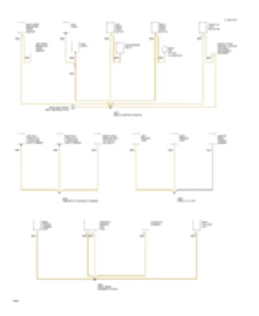
GROUND DISTRIBUTION
Ground Distribution Wiring Diagram (1 of 5) for Mercedes-Benz 500E 1993
List of elements for Ground Distribution Wiring Diagram (1 of 5) for Mercedes-Benz 500E 1993:
- (400e)
- (500e)
- (except 400e/500e)
- 1995 vftc c
- 400e/500e
- 4matic control unit
- A/c compressor control unit (diesel)
- A/c compressor/ boost cut-out microswitch
- Abs control unit
- Abs control unit (except 400e/500e)
- Abs/asr control unit
- Abs/asr control unit (except 400e/500e)
- Air injec. pump switch- over valve (gasoline except 400e/ 500e)
- Air injection pump switchover valve
- Base module
- Battery
- Cis-e control unit (gasoline except 400e/ 500e)
- Cruise control/ idle speed control unit
- Diagnostic module
- Eds control unit (diesel)
- Electro- magnetic air injec. pump clutch (gasoline except 400e/ 500e)
- Electrolytic capacitor
- Electromagnetic accelerator/ cruise control unit
- Electromagnetic air injection pump clutch
- Electronic accelerator control unit
- Engine systems control unit (mas) (gasoline except 400e/ 500e)
- G101 (400e/500e) (right side of component compartment, on module box bracket)
- G103 (400e/500e) (right side of component compartment, on shock tower)
- G103 (right side of component compartment, rear of shock tower)
- Heated o-sensor (gasoline except 400e/ 500e)
- Heated oxygen sensor
- Hood switch
- Horn alarm
- Lh control unit
- Module box blower motor
- Over- voltage protection relay
- Stop lamp switch
- Test connection for diagnosis
Ground Distribution Wiring Diagram (2 of 5) for Mercedes-Benz 500E 1993
List of elements for Ground Distribution Wiring Diagram (2 of 5) for Mercedes-Benz 500E 1993:
- 1995 vftc c
- Abs hydraulic unit
- Abs/asr hydraulic unit
- Auxiliary fan
- Braided
- Cis-e control unit (except 400e/ 500e)
- Coolant level switch
- Coolant temperature sensor
- Deceleration microswitch
- Diagnostic socket/ terminal block
- Electrotronic ignition control unit (gasoline)
- Ezl/akr control unit (except 400e/ 500e)
- Fuse/ relay box
- G100 (lower left front corner of engine compartment, on abs hydraulic unit bracket)
- G101 (lower right front of engine compartment)
- G106 (lower left front of engine compartment, near headlamp)
- G110 (left front of engine, on intake manifold)
- Headlamp washer pump (diesel)
- Headlamp washer pump (gasoline)
- Headlamp washer relay
- Left headlamp unit
- Left headlamp wiper motor
- Module box blower motor
- Preglow time relay (diesel)
- Reference resistor (ezl) (gasoline)
- Refrigerant high pressure switch
- Right front brake pad wear sensor
- Right headlamp unit
- Right headlamp wiper motor
- Throttle valve switch
- Two-tone horn
- Washer fluid level switch
- Washer fluid level switch (diesel)
- Windshield washer pump (diesel)
- Windshield washer pump (gasoline)
Ground Distribution Wiring Diagram (3 of 5) for Mercedes-Benz 500E 1993
List of elements for Ground Distribution Wiring Diagram (3 of 5) for Mercedes-Benz 500E 1993:
- 1995 vftc c
- Anti-theft alarm control unit
- Automatic antenna switch
- Brake fluid level switch
- Combination relay
- Convenience relay
- Cruise control actuator
- Cruise control amplifier
- Electronic blower control unit
- Exterior lamp failure monitoring unit
- Exterior lamp switch illumination
- Front cigar lighter with ashtray illumination
- Fuse/ relay box
- G202 (left side of instrument cluster)
- Glove box lamp with switch
- Heated windshield washer nozzle thermoswitch
- Instrument cluster
- J/b
- Left air outlet illumination
- Left front brake pad wear sensor
- Left front door actuator
- Left front door switch
- Left front door switch (anti-theft alarm)
- Left front memory seat control unit
- Left front power seat control unit
- Left front power seat switch
- Left outside heated mirror
- Outside mirror control switch
- Outside temperature sensor
- Parking brake switch
- Power seat relay
- Radio
- Rear dome lamp switch
- Rear head restraint release switch
- Rear window sun shade switch
- Right front door actuator
- Right front door switch (anti-theft alarm)
- Right front power seat switch
- Right rear view mirror
- Sedan, coupe
- Shift pattern illumination
- Snow chain switch
- Speed sensor
- Tailgate switch
- Telescopic steering column switch
- Transmission overload protection switch
- Trunk lid lock switch
- Wagon
- Warning buzzer switch
- Warning module
- Wiper motor
- X30
- X64
Ground Distribution Wiring Diagram (4 of 5) for Mercedes-Benz 500E 1993
List of elements for Ground Distribution Wiring Diagram (4 of 5) for Mercedes-Benz 500E 1993:
- 1995 vftc c
- Ashtray illumination
- Aspirator blower
- Cd changer
- Center air outlet illumination
- Convenience control unit
- Driver seat belt buckle switch (coupe only)
- Fader
- Front seat heater control unit
- Hazard flasher switch
- Head restraint release valve w/ shut off delay
- Head restraint valve with shut-off delay
- Heated rear window switch
- Illuminated automatic antenna switch
- Left audio power amplifier
- Left front backrest heater
- Left front power window switch
- Left front seat heater switch
- Left rear door switch
- Left rear power window switch
- Nca
- Radio
- Rear dome lamp switch
- Rear head restraint release switch
- Rear window washer switch
- Rear window wiper switch
- Resistor
- Right air outlet illumination
- Right audio power amplifier
- Right front backrest heater
- Right front door actuator
- Right front door switch
- Right front power window switch
- Right front seat heater switch
- Right rear door switch
- Right rear power window switch
- Safety switch, rear power window
- Shift pattern illumination
- To g302
- Tuner/ amplifier
Ground Distribution Wiring Diagram (5 of 5) for Mercedes-Benz 500E 1993
List of elements for Ground Distribution Wiring Diagram (5 of 5) for Mercedes-Benz 500E 1993:
- 1995 vftc c
- Automatic antenna
- Convenience relay
- From right front seat heater switch
- Front dome reading lamp (with shut- off delay)
- Fuel pump 1
- Fuel pump 2
- G302 (below center console)
- G405 (right rear corner of trunk)
- G905 (right 'c' pillar)
- G908 (center of windshield header)
- Heated rear window element
- Left front door switch
- Left reading lamp
- Left rear brake pad wear sensor
- Left sun visor (with illuminated vanity mirror)
- Rear window washer pump
- Right air outlet illumination
- Right front door switch
- Right reading lamp
- Right rear brake pad wear sensor
- Right sun visor (with illuminated vanity mirror)
- Right taillamp unit
- Transmit/ receive unit (tru)
- Trunk lid lock actuator
HEADLIGHTS
Headlight Wiring Diagram, with DRL for Mercedes-Benz 500E 1993
List of elements for Headlight Wiring Diagram, with DRL for Mercedes-Benz 500E 1993:
- 56a
- 56b
- 58l
- 58r
- C 1995 vftc
- Charging system
- Combination switch
- Daytime driving lamp control unit (behind front passenger footrest)
- Exterior lamp failure monitoring unit (in fuse/ relay box)
- Exterior lamp switch
- Exterior lights switch
- Flash
- Fog lamp
- Fuse 16a
- Fuse 8a
- Fuse/ relay box (left side of component compartment)
- G106 (at left headlamp unit)
- G107 (at right headlamp unit)
- G202 (behind left side of instrument cluster)
- Head
- High
- High beam indicator
- Hot at all times
- Hot in accy, run or start
- Hot in off or accy
- Hot in run or start
- Instrument cluster
- Interior lights system
- K30
- Left headlamp unit
- Low
- Nse
- Off
- P30
- Park
- Red
- Right headlamp unit
- Terminal block (top of driver's footwell, forward of parking brake lever)
Headlight Wiring Diagram, without DRL for Mercedes-Benz 500E 1993
List of elements for Headlight Wiring Diagram, without DRL for Mercedes-Benz 500E 1993:
- 56a
- 56b
- 58l
- Anti- theft system
- C 1995 vftc
- Combination switch
- Exterior lamp failure monitoring unit (in fuse/ relay box)
- Exterior lamp switch
- Flash
- Fog
- Fog lamp
- Fuse 16a
- Fuse 8a
- Fuse/ relay box (left side of component compartment)
- G106 (at left headlamp unit)
- G107 (at right headlamp unit)
- G202 (behind left side of instrument cluster)
- Head
- High
- High beam indicator
- Hot at all times
- Hot in accy, run or start
- Hot in park or head
- Instrument cluster
- Left headlamp unit
- Low
- Nse
- Off
- Park
- Right headlamp unit
HORN
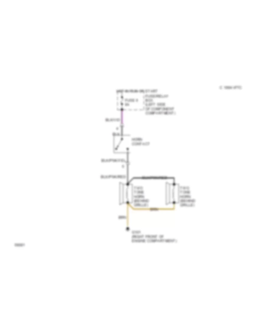
Horn Wiring Diagram for Mercedes-Benz 500E 1993
List of elements for Horn Wiring Diagram for Mercedes-Benz 500E 1993:
- 1994 vftc c
- Fuse 6 8a
- Fuse/relay box (left side of component compartment)
- G101 (right front of engine compartment)
- Horn contact
- Hot in run or start
- Two tone horn (behind grille)
INSTRUMENT CLUSTER
Instrument Cluster Wiring Diagram for Mercedes-Benz 500E 1993
List of elements for Instrument Cluster Wiring Diagram for Mercedes-Benz 500E 1993:
- (fuse/relay box)
- (left side of instrument cluster)
- (right side of component compt, behind battery)
- (sedan: left side of trunk, below hinge) (wagon: behind left rear quarter panel)
- (top of brake fluid reservoir)
- 4-matic function indicator
- 4-matic indicator
- 56a
- 58d
- Abs indicator
- Anti-lock brakes system
- Asd function indicator
- Asr function indicator
- Asr indicator
- Audible turn signal indicator
- Brake fluid & park brake indicator
- Brake fluid level switch
- Brake pad wear indicator
- C10
- C11
- C12
- C13
- C14
- C15
- C6 x7
- Charge indicator
- Cis-e control unit
- Coolant level indicator
- Coolant level switch (lower front of coolant reservoir)
- Coolant temperature gauge
- Coolant temperature gauge sensor (left side of engine, above intake manifold)
- Electronic clock/ tachometer
- Electronic speedometer w/ top speed limiter
- Engine controls system (tach signal)
- Engine indicator o2/check
- Exterior lamp failure ind
- Exterior lamp failure module
- Exterior lights system
- First gear start relay
- Fluid reservoir)
- Fuel gauge
- Fuel level sensor (top of fuel tank)
- Fuel reserve indicator
- Fuse 8a
- Fuse/ relay box
- G101 (lower right front of engine compt)
- G101 g106 (diesel) (gas) (lower (lower left front of eng compt) front of engine compt)
- G202
- G202 (left side of instrument cluster)
- G302 (below center console)
- G404
- Headlights system
- High beam indicator
- Hot at all times
- Hot in run or start
- Illumination
- Indicator asd
- Indicator srs
- Inductive speed sensor (left side of transmission)
- Instrument cluster
- Instrument cluster)
- Interior lights system
- J/b x35/5 (right side of
- Left front brake pad wear sensor (in left front brake pad)
- Left rear brake pad brake pad wear sensor wear sensor (in left rear brake pad) brake pad)
- Left turn indicator
- Nca
- Nca nca
- Oil level indicator
- Oil level switch (left side of
- Oil pan)
- Oil pressure gauge
- Oil pressure sensor (at base of oil filter housing)
- Outside temp sensor (left corner of front bumper)
- Outside temperature display
- Parking brake switch (left kick panel)
- Pnk
- Pnk/red
- Radio
- Rheostat
- Right
- Right front brake pad wear sensor (in right front brake pad)
- Right rear brake pad wear sensor (in right rear brake pad)
- Right turn indicator
- Starting/charging system
- Tempmatic pushbutton control unit
- Transmission system
- Washer fluid level
- Windshield washer fluid indicator
INTERIOR LIGHTS
Interior Light Wiring Diagram (1 of 2) for Mercedes-Benz 500E 1993
List of elements for Interior Light Wiring Diagram (1 of 2) for Mercedes-Benz 500E 1993:
- (center of windshield header)
- (left side of instrument cluster)
- (right side of instrument cluster)
- 58r
- 58d
- Anti- theft alarm control unit x2
- Anti-theft system
- Automatic antenna
- C13
- Cigar lighter illumination
- Convenience control unit
- Convenience relay
- Dome lamp
- Dome/reading lamps
- Exterior lamp failure monitoring unit (fuse/relay box)
- Exterior lamp switch
- From terminal block x6/1
- Fuse 16a
- Fuse 8a
- Fuse c 16a
- Fuse/ relay box
- Fuse/relay box
- G202
- G202 (left side of instrument cluster)
- G302 (behind center console)
- G302 (below center console)
- G404 (left side of trunk, below hinge)
- G908
- Glove box lamp
- Head
- Hot at all times
- Hot in accy, run or start
- Hot in off & acc
- Hot in run or start
- Illumination
- Instrument cluster
- J/c x30 (left kick panel)
- K30
- Left front door switch
- Left front exit lamp
- Left rear door switch
- Left rear exit lamp
- Left vanity lamp
- Off
- P30
- Park
- Power seat relay (fuse/relay box)
- Reading lamp
- Rear dome lamp
- Rear dome lamp switch
- Rheostat
- Right air out- let illumination
- Right front door switch
- Right front exit lamp
- Right rear door switch
- Right rear exit lamp
- Right vanity lamp
- Seat belt indicators
- To terminal block x6
- Trunk lamp
- Trunk lamp switch
- Warning module
- Warning module (behind right side of instrument cluster)
Interior Light Wiring Diagram (2 of 2) for Mercedes-Benz 500E 1993
List of elements for Interior Light Wiring Diagram (2 of 2) for Mercedes-Benz 500E 1993:
- (left side of g202 instrument cluster)
- 58d
- Center air outlet control illumination
- Exterior lamp switch illumination
- Fader
- Fresh air/ recircu- lation switch
- From instrument a cluster rheostat
- Fuse 8a
- Fuse/ relay box
- G202 (left side of instrument cluster)
- G302 (below center console)
- Hazard flasher switch
- Heated rear window switch
- Hot at all times
- Instrument cluster
- Instrument illumination control unit (behind instrument cluster, on steering column)
- J/c x30 (left kick panel)
- Left air outlet illumination
- Left front power window switch
- Left front seat heater switch
- Left rear power window switch
- Left rear power window switch (front console)
- Nca
- Off
- Outside temperature display
- Push- button control unit
- Radio
- Rear window sunshade switch
- Red
- Right air outlet illumination
- Right front door switch
- Right front power window switch
- Right front seat heater switch
- Right rear power window switch
- Right rear power window switch (front console)
- Safety switch rear power windows
- Shift illumination
- Sliding pop-up roof switch
- Terminal block x6 (below radio)
- Terminal block x6/1 (left of ashtray)
- To accessory harnesses
- To rear dome lamp switch
MEMORY SYSTEMS
Left Front Seat & Power Steering Column Wiring Diagram for Mercedes-Benz 500E 1993
List of elements for Left Front Seat & Power Steering Column Wiring Diagram for Mercedes-Benz 500E 1993:
- Anti-theft alarm control unit (behind front passenger footrest)
- Auxiliary fuse holder
- Backrest
- Front seat height
- Fuse 16a
- Fuse 8a
- Fuse e 25a
- Fuse f 25a
- Fuse/ relay box (left side of component compartment)
- G202 (behind left side of instrument cluster)
- G302 (below center console)
- Head restraint up/dn
- Hot at all times
- Hot in accy, run or start
- Interior lights system
- Left front door switch
- Left front power seat motor group with memory
- Left front power seat switch
- Left front seat memory control unit (under driver's seat)
- Pnk
- Power seat relay
- Rear seat height
- Red
- Right front door switch
- Right power seat circuit
- Seat fwd/back
- Solid state
- Telescopic steering column motor (left side of steering column)
- Telescopic steering column switch
- Terminal block (top of driver's footwell)
- Warning module (behind right side of i/p)
POWER ANTENNA
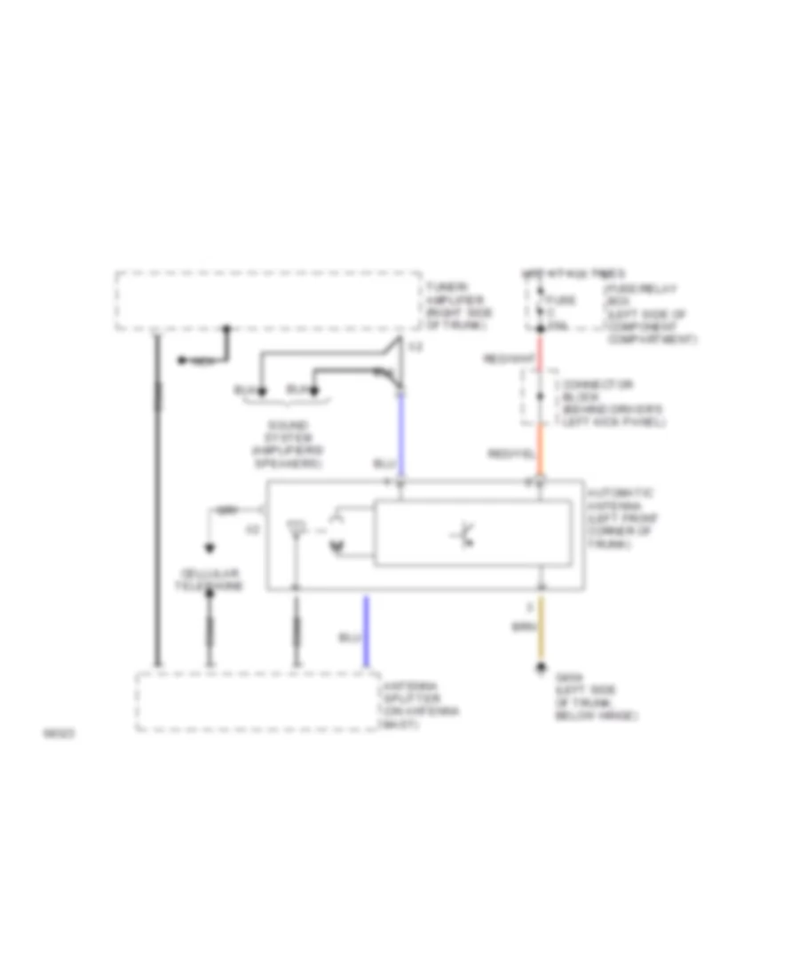
Power Antenna Wiring Diagram for Mercedes-Benz 500E 1993
List of elements for Power Antenna Wiring Diagram for Mercedes-Benz 500E 1993:
- Antenna splitter (on antenna mast)
- Automatic antenna (left front corner of trunk)
- Cellular telephone
- Coax
- Connector block (behind driver's left kick panel)
- Fuse c 16a
- Fuse/relay box (left side of component compartment)
- G404 (left side of trunk, below hinge)
- Hot at all times
- Nca
- Sound system (amplifiers/ speakers)
- Tuner/ amplifier (right side of trunk)
POWER DISTRIBUTION
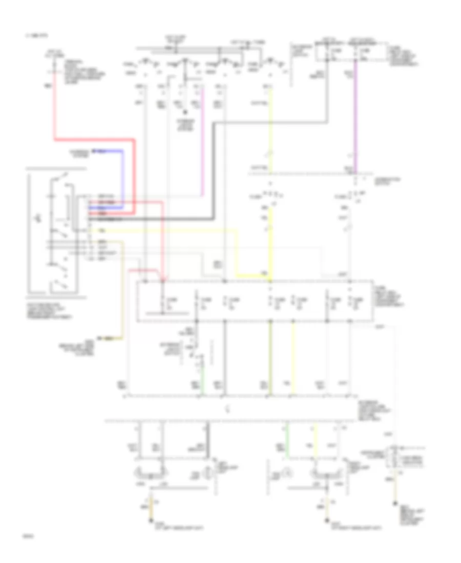
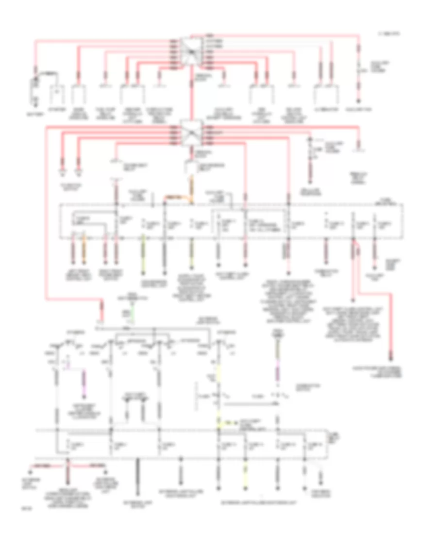
Power Distribution Wiring Diagram (1 of 2) for Mercedes-Benz 500E 1993
List of elements for Power Distribution Wiring Diagram (1 of 2) for Mercedes-Benz 500E 1993:
- (400e/500e)
- (all others)
- 16a
- 1995 vftc c
- 30a
- 58l
- 58r
- Abs hydraulic unit (w/o asr)
- Abs/asr hydraulic unit (with asr)
- Alternator
- Anti-theft alarm control unit
- Anti-theft alarm control unit
- Anti-theft alarm system
- Audio power amplifier(s), cd changer, tuner/amplifier
- Auxiliary fan
- Auxiliary fan relay (except 400e/500e)
- Auxiliary fuse holder
- Base module (gasoline)
- Battery
- Cellular telephone
- Combination relay
- Combination switch
- Convenience control unit
- Convenience relay
- Except 400e/ 500e
- Exterior lamp failure monitoring unit
- Exterior lamp switch
- Ezl/akr ignition control unit (gasoline)
- Flash
- From fuse 2
- From ignition switch
- Fuel pump relay (gasoline)
- Fuse 10 25a
- Fuse 11 25a
- Fuse 12 25a
- Fuse 13 8a
- Fuse 14 8a
- Fuse 15 8a
- Fuse 16 8a
- Fuse 3 8a
- Fuse 4 8a
- Fuse 8 8a
- Fuse 9 8a
- Fuse a 16a
- Fuse c 16a
- Fuse d 16a
- Fuse e 25a
- Fuse f 25a
- Fuse f 8a
- Fuse g 25a
- Fuse h 25a
- Fuse/ relay box
- Head
- Headlamp wiper/washer motors, headlamp washer relay lamps: park/tail/ side marker/license
- High beam indicator
- Instrument cluster/ center console illumination
- K30
- Left front memory seat control unit
- Off
- Overvoltage protection relay (diesel)
- P30
- Park
- Power seat relay
- Preglow relay (diesel)
- Radio, warning buzzer switch, power seat relay, convenience relay, instrument illumination control unit, hazard flasher switch, instrument cluster, front dome reading light, sun visors, diagnostic socket/ terminal block, amplifier control unit
- Red
- Right front power seat switch
- Standing
- Starter
- Terminal block
- To ignition switch
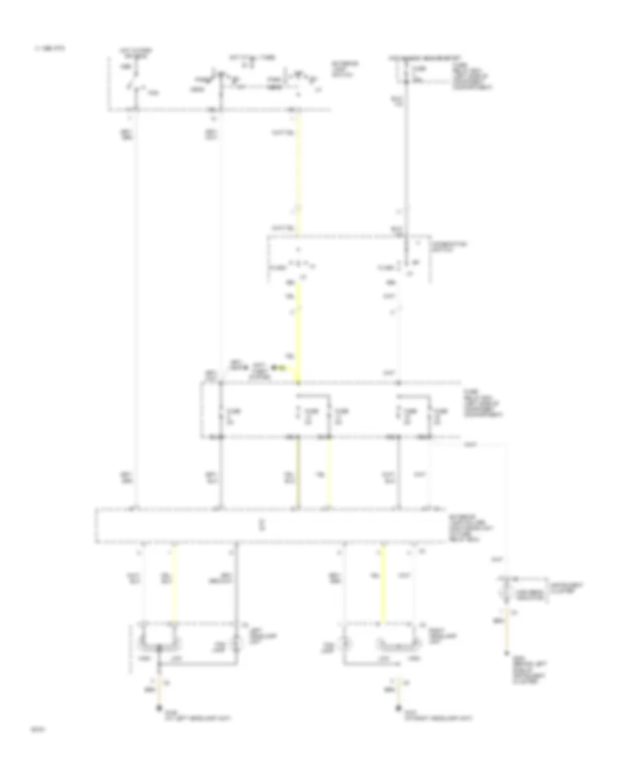
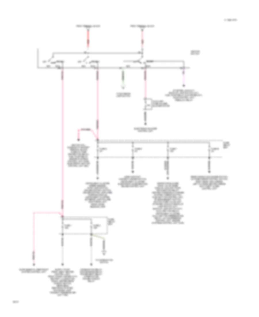
Power Distribution Wiring Diagram (2 of 2) for Mercedes-Benz 500E 1993
List of elements for Power Distribution Wiring Diagram (2 of 2) for Mercedes-Benz 500E 1993:
- 15a
- 15r
- 15x
- 1995 vftc c
- Acc
- Aspirator blower, mono valve, base module, coolant pump, air injection relay, heated windshield washer system thermo switch, push button control unit, "b" engagement switch, switch over valve unit, starter lock-out/back-up lamp switch (a/t), back-up lamp switch (m/t), auxiliary fan relay, instrument cluster, auxiliary fan preresistor relay, a/c compressor control unit, engine systems control unit (mas)
- Auxiliary fuse holder, blower motor
- Combination relay, convenience relay, power seat relay, wiper motor, power window relay
- Electronic blower control unit
- From terminal block
- Fuse 1 16a
- Fuse 2 16a
- Fuse 5 8a
- Fuse 6 8a
- Fuse 7 16a
- Fuse b 8a
- Fuse/ relay box
- Horn contact, hazard flasher switch, instrument cluster, electronic accelerator/ cruise control unit
- Ignition coil, diagnostic socket/ terminal block, overvoltage protection relay, fuel pump relay, engine systems control unit (mas), electronic ignition control unit (ezl)
- Ignition switch
- Instrument cluster, speed sensor, stop lamp switch, cruise control switch, cruise control amplifier, warning module, instrument cluster, exterior lamp failure monitoring unit, front dome/ reading lamp
- Off
- Pnk/red
- Rear window sun shade switch, outside mirror control switch, right rear view mirror, left outside heated mirror, anti-theft alarm control unit
- Red
- Run
- Start
- Starter lock-out/ back-up lamp switch (a/t), fuel pump relay & starter (m/t), cis-e control unit, preglow relay
- To combination switch
- To exterior lamp switch
POWER DOOR LOCKS
Power Door Lock Wiring Diagram for Mercedes-Benz 500E 1993
List of elements for Power Door Lock Wiring Diagram for Mercedes-Benz 500E 1993:
- 1994 vftc c
- Anti-theft alarm control unit
- Door lock
- Electrical center (left side of component compartment)
- Fuse a 16a
- Fuse c 8a
- G302 (behind lower front of console)
- Gas cap actuator
- Gas cap flap
- Hot at all times
- Hot in run or start
- Left front door actuator
- Left rear door actuator
- Lid lock
- Lock
- Only
- Power seats (seat regulating valve)
- Right front door actuator
- Right rear door actuator
- Solid state
- Trunk/ tailgate lid lock actuator
- Un- lock
- Vacuum actuator
- W/ orthopedic seats
- Warning buzzer switch (dash panel, right of steering column)
POWER MIRRORS
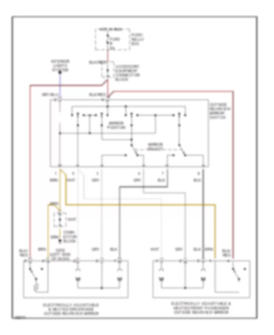
Power Mirror Wiring Diagram for Mercedes-Benz 500E 1993
List of elements for Power Mirror Wiring Diagram for Mercedes-Benz 500E 1993:
- Accessory equipment connector block
- Block
- Electrically adjustable & heated driver-side outside rearview mirror
- Electrically adjustable & heated front passenger outside rearview mirror
- Fuse b 8a
- Fuse/ relay box
- G202 (left side of dash)
- Hot in run
- Interior lights system
- Mirror position
- Mirror select
- Outside rearview mirror switch
POWER SEATS
Driver Power Seat Wiring Diagram for Mercedes-Benz 500E 1993
List of elements for Driver Power Seat Wiring Diagram for Mercedes-Benz 500E 1993:
- Anti-theft alarm control unit (behind front passenger footrest)
- Auxiliary fuse holder
- Backrest
- Front seat height
- Fuse 16a
- Fuse 8a
- Fuse e 25a
- Fuse f 25a
- Fuse/ relay box (left side of component compartment)
- G202 (behind left side of instrument cluster)
- G302 (below center console)
- Head restraint up/down
- Hot at all times
- Hot in accy, run or start
- Left front door switch
- Left front power seat motor group (below right front seat)
- Left front power seat switch
- Left front seat connector (below left front seat)
- Pnk
- Power seat relay
- Rear seat height
- Red
- Right front door switch
- Right power seat circuit
- Seat forward/ backward
- Solid state
- Terminal block (top of driver's footwell)
- Warning module (behind right side of i/p)
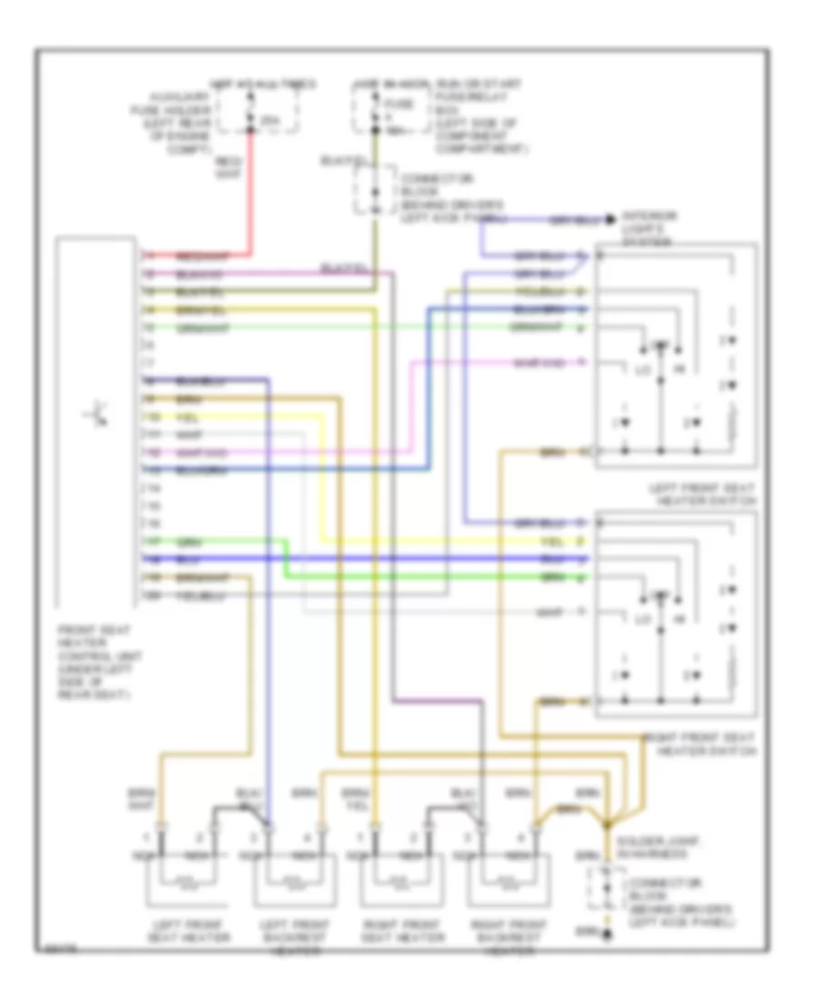
Heater Wiring Diagram for Mercedes-Benz 500E 1993
List of elements for Heater Wiring Diagram for Mercedes-Benz 500E 1993:
- 25a
- Auxiliary fuse holder (left rear of engine compt)
- Connector block (behind driver's left kick panel)
- Front seat heater control unit (under left side of rear seat)
- Fuse a 16a
- Hot at all times
- Hot in accy, run or start fuse/relay box (left side of component compartment)
- Interior lights system
- Left front backrest heater
- Left front seat heater
- Left front seat heater switch
- Nca
- Off
- Right front backrest heater
- Right front seat heater
- Right front seat heater switch
- Solder joint, in harness
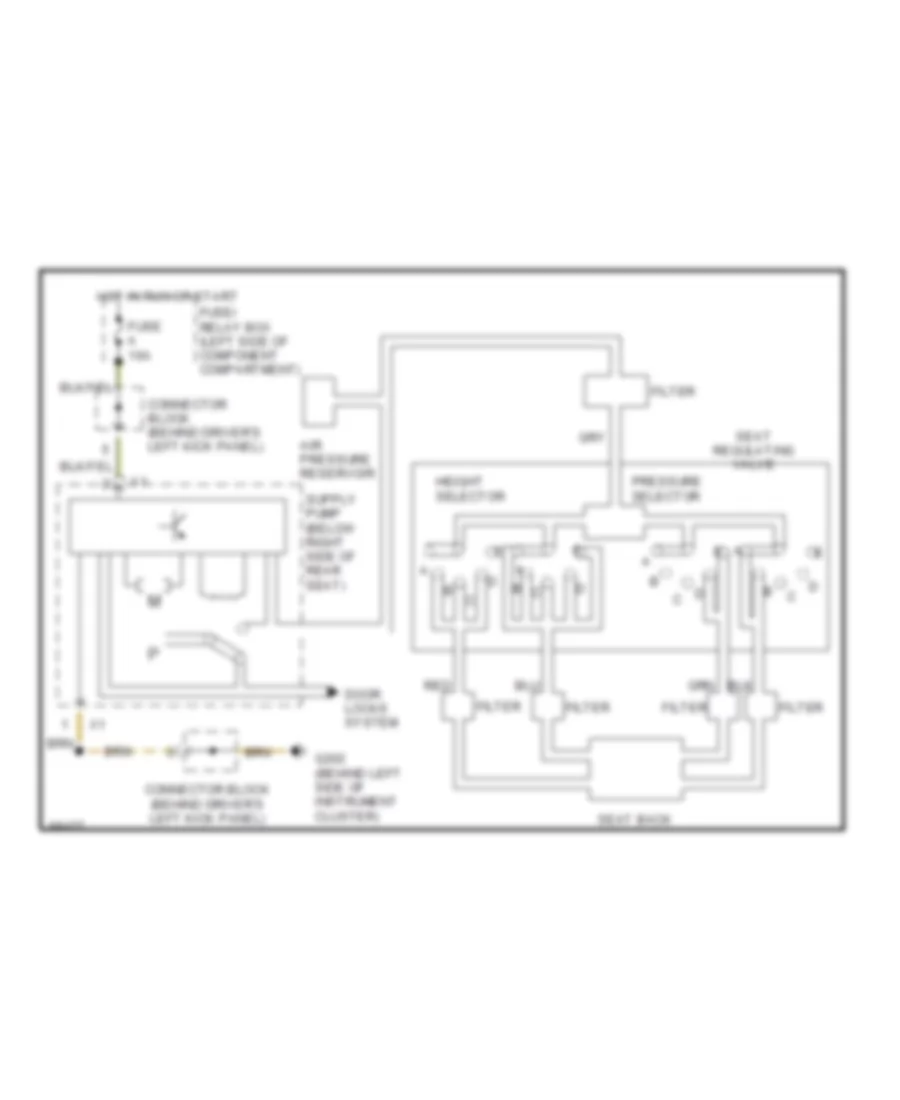
Orthopedic Seats for Mercedes-Benz 500E 1993
List of elements for Orthopedic Seats for Mercedes-Benz 500E 1993:
- Air pressure reservoir
- Connector block (behind driver's left kick panel)
- Door locks system
- Filter
- Fuse a 16a
- Fuse/ relay box (left side of component compartment)
- G202 (behind left side of instrument cluster)
- Height selector
- Hot in run or start
- Pressure selector
- Red
- Seat back
- Seat regulating valve
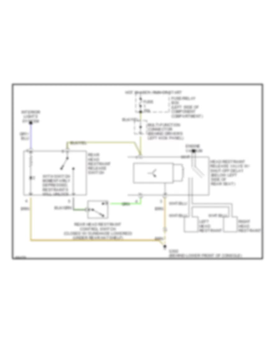
Rear Head Restraint Wiring Diagram for Mercedes-Benz 500E 1993
List of elements for Rear Head Restraint Wiring Diagram for Mercedes-Benz 500E 1993:
- Engine vacuum
- Fuse 16a
- Fuse/relay box (left side of component compartment)
- G302 (behind lower front of console)
- Head restraint release valve w/ shut-off delay (below left side of rear seat)
- Hot in accy, run or start
- Interior lights system
- Left head restraint
- Multi-function connector (behind driver's left kick panel)
- Rear head restraint control switch (closed w/ sunshade lowered) (under rear hatshelf)
- Rear head restraint release switch
- Right head restraint
- With switch momentarily depressed, restraints will unlock
Right Seat Wiring Diagram for Mercedes-Benz 500E 1993
List of elements for Right Seat Wiring Diagram for Mercedes-Benz 500E 1993:
- Anti-theft alarm control unit (behind front passenger footrest)
- Auxiliary fuse holder
- Backrest
- Front seat height
- Fuse 16a
- Fuse 8a
- Fuse e 25a
- Fuse f 25a
- Fuse/ relay box (left side of component compartment)
- G202 (behind left side of instrument cluster)
- G302 (below center console)
- Head restraint up/down
- Hot at all times
- Hot in accy, run or start
- Left front door switch
- Left power seat circuit
- Pnk
- Power seat relay
- Rear seat height
- Red
- Right front door switch
- Right front power seat motor group (below right front seat)
- Right front power seat switch
- Right front seat connector (below left front seat)
- Seat forward/ backward
- Solid state
- Terminal block (top of driver's footwell)
- Warning module (behind right side of i/p)
POWER TOP/SUNROOF
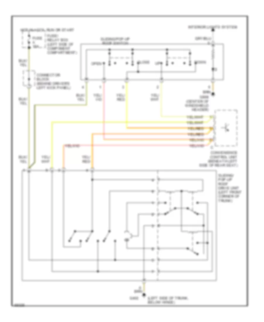
Power Top/Sunroof Wiring Diagrams for Mercedes-Benz 500E 1993
List of elements for Power Top/Sunroof Wiring Diagrams for Mercedes-Benz 500E 1993:
- (left side of trunk, below hinge)
- Close
- Connector block (behind driver's left kick panel)
- Convenience control unit (beneath left side of rear seat)
- Down
- Fuse a 16a
- Fuse/ relay box (left side of component compartment)
- G402
- G908 (center of windshield header)
- Hot in accy, run or start
- Interior lights system
- Open
- Sliding/ pop-up roof drive unit (left front corner of trunk)
- Sliding/pop-up roof switch
Sunroof Wiring Diagram for Mercedes-Benz 500E 1993
List of elements for Sunroof Wiring Diagram for Mercedes-Benz 500E 1993:
- (left side of trunk, below hinge)
- Close
- Connector block (behind driver's left kick panel)
- Convenience control unit (beneath left side of rear seat)
- Down
- Fuse a 16a
- Fuse/ relay box (left side of component compartment)
- G402
- G908 (center of windshield header)
- Hot in accy, run or start
- Interior lights system
- Open
- Sliding/ pop-up roof drive unit (left front corner of trunk)
- Sliding/pop-up roof switch
POWER WINDOWS
Power Window Wiring Diagram for Mercedes-Benz 500E 1993
List of elements for Power Window Wiring Diagram for Mercedes-Benz 500E 1993:
- (behind lower
- Auto dn
- Battery
- Convenience control unit (beneath left side of rear seat)
- Convenience relay (rear of fuse box)
- Front of console)
- Fuse 2 16a
- Fuse 9 8a
- Fuse a 16a
- Fuse g 25a
- Fuse h 25a
- Fuse/relay box (left side of component compartment)
- G101 (right shock tower)
- G302
- G302 (behind lower front of console)
- Hot at all times
- Hot in acc, run and start
- Interior lights system
- Left front door switch
- Left front power window motor
- Left front power window switch
- Left rear power window motor
- Left rear power window switch (console)
- Left rear power window switch (door)
- Red
- Right front power window motor
- Right front power window switch
- Right rear power window motor
- Right rear power window switch (console)
- Right rear power window switch (door)
- Safety switch, rear power windows
- Solid state
- Terminal block (center of dashboard)
STARTING/CHARGING
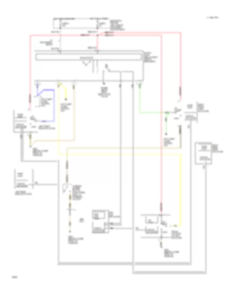
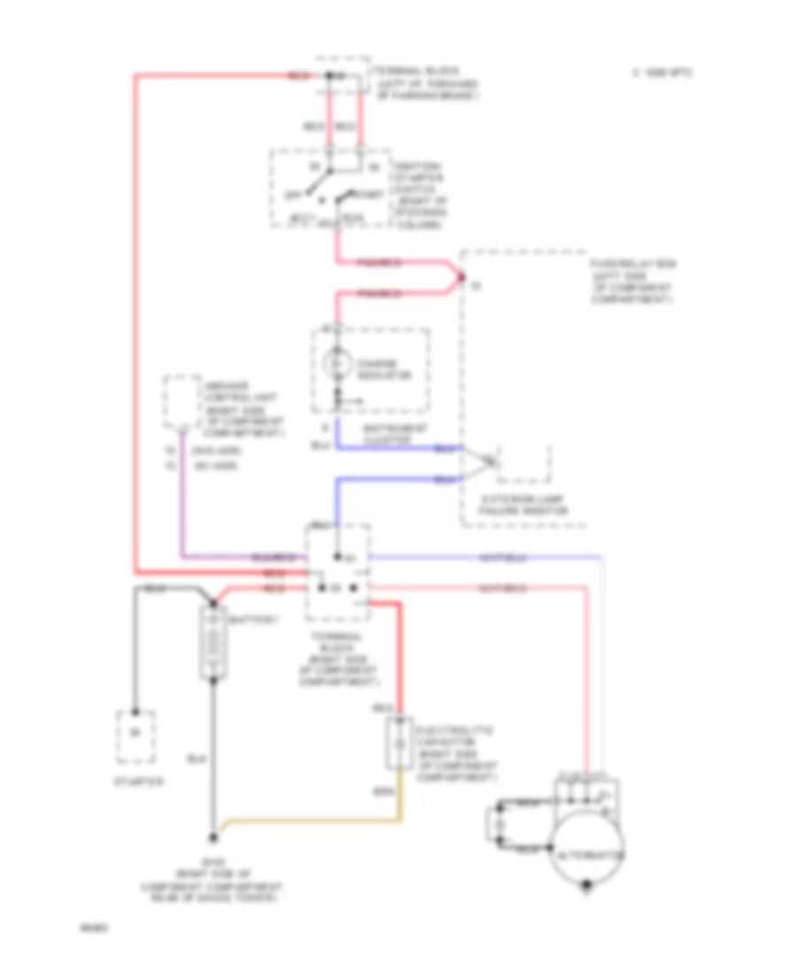
Charging Wiring Diagram for Mercedes-Benz 500E 1993
List of elements for Charging Wiring Diagram for Mercedes-Benz 500E 1993:
- (left i/p, forward of parking brake)
- (left side
- (right of steering column)
- (right side
- (w/ asr)
- (w/o asr)
- Abs/asr control unit
- Accy
- Alternator
- Battery
- C 1995 vftc
- Charge indicator
- Component compartment, rear of shock tower)
- Electrolytic capacitor
- Exterior lamp failure monitor
- Fuse/relay box
- G103 (right side of
- Ignition/ starter switch
- Instrument cluster
- Nca
- Of component compartment)
- Off
- Pnk/red
- Red
- Run
- Start
- Starter
- Terminal block
- Terminal block (right side of component compartment)
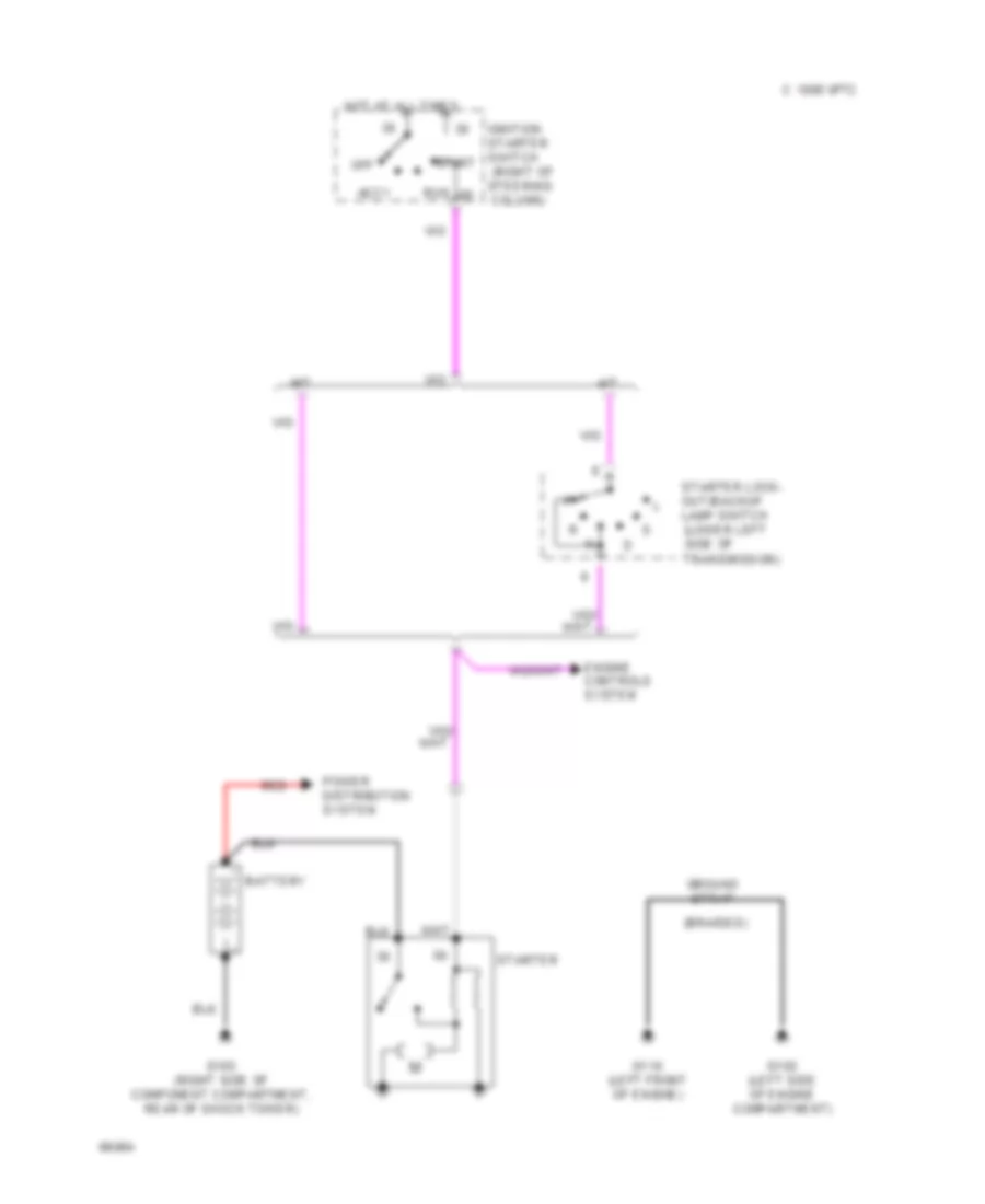
Starting Wiring Diagram for Mercedes-Benz 500E 1993
List of elements for Starting Wiring Diagram for Mercedes-Benz 500E 1993:
- (braided)
- (lower left
- (right of steering column)
- A/t
- Accy
- Battery
- C 1995 vftc
- Controls
- Distribution
- Engine
- G102 (left side of engine compartment)
- G103 (right side of component compartment, rear of shock tower)
- G110 (left front of engine)
- Ground strap
- Hot at all times
- Ignition starter switch
- M/t
- Off
- Power
- Red
- Run
- Side of
- Start
- Starter
- Starter lock- out/backup lamp switch
- System
- Transmission)
SUPPLEMENTAL RESTRAINTS
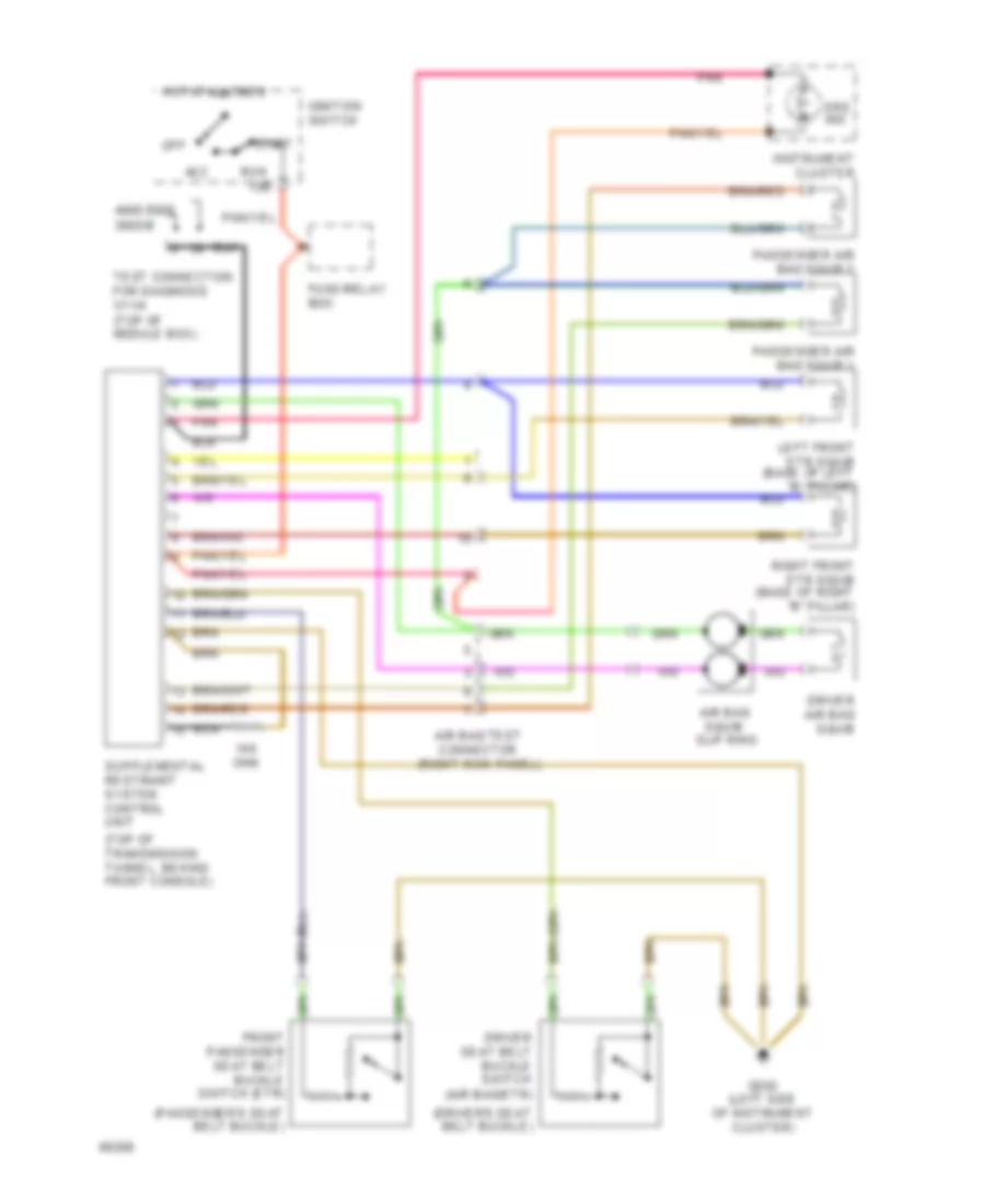
Supplemental Restraint Wiring Diagram for Mercedes-Benz 500E 1993
List of elements for Supplemental Restraint Wiring Diagram for Mercedes-Benz 500E 1993:
- (driver's seat belt buckle)
- (passenger's seat belt buckle)
- (top of transmission tunnel, behind front console)
- 15r
- 300d/e
- 400e/500e
- Acc
- Air bag squib slip ring
- Air bag test connector (right kick panel)
- Driver air bag squib
- Driver seat belt buckle switch (air bag/etr)
- Front passenger seat belt buckle switch (etr)
- Fuse/relay box
- G202 (left side of instrument cluster)
- Hot at all times
- Ignition switch
- Instrument cluster
- Left front etr squib (base of left "b" pillar)
- Nca
- Off
- Ohm
- Passenger air bag squib 1
- Passenger air bag squib 2
- Pnk
- Right front etr squib (base of right "b" pillar)
- Run
- Srs ind
- Start
- Test connection for diagnosis x11/4 (top of module box)
WARNING SYSTEMS
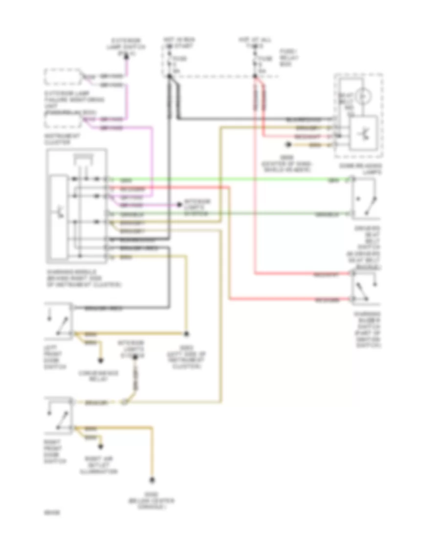
Warning System Wiring Diagrams for Mercedes-Benz 500E 1993
List of elements for Warning System Wiring Diagrams for Mercedes-Benz 500E 1993:
- C13
- Convenience relay
- Dome/reading lamps
- Driver's seat belt switch (in driver's seat belt buckle)
- Exterior lamp failure monitoring unit (fuse/relay box)
- Exterior lamp switch (pin 4)
- Fuse 8a
- Fuse/ relay box
- G202 (left side of instrument cluster)
- G302 (below center console)
- G908 (center of wind- shield header)
- Hot at all times
- Hot in run or start
- Instrument cluster
- Interior lights system
- Left front door switch
- Right air outlet illumination
- Right front door switch
- Seat belt ind x3
- Warning buzzer switch (part of ignition switch)
- Warning module (behind right side of instrument cluster)
- X1/4
WIPER/WASHER
Front Wiper/Washer Wiring Diagram for Mercedes-Benz 500E 1993
List of elements for Front Wiper/Washer Wiring Diagram for Mercedes-Benz 500E 1993:
- 1994 vftc c
- Combi- nation switch
- Combination relay (in fuse/ relay box)
- Fuse 16a
- Fuse/ relay box (left side of component compartment)
- G101 (right front of engine compartment)
- G202 (behind left side of i/p)
- Headlight wiper/washer circuit
- Hot in accy,run or start
- Int
- Off
- Park
- Run
- Washer switch
- Windshield washer pump (front of washer fluid reservoir)
- Wiper motor (left side of component compartment)
- Wiper switch
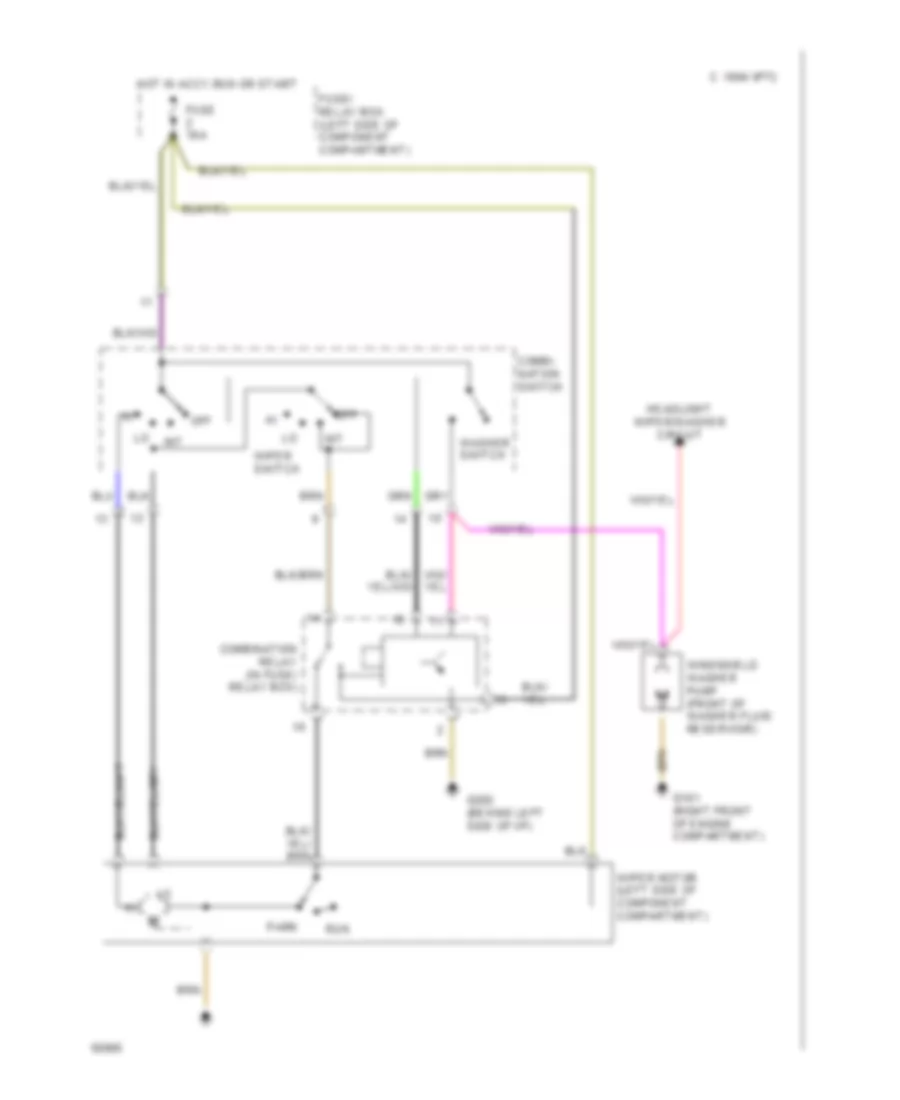
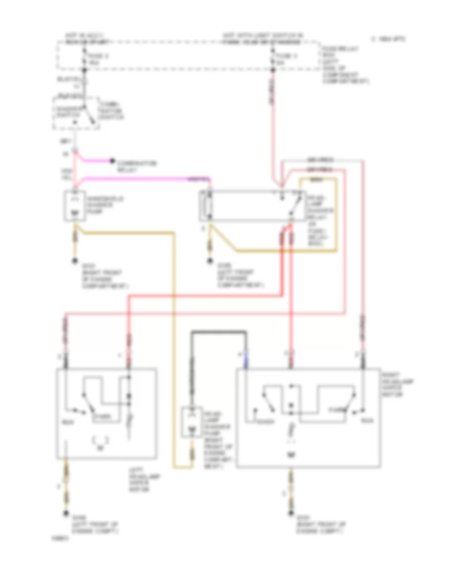
Headlight Washer/Wiper Wiring Diagram for Mercedes-Benz 500E 1993
List of elements for Headlight Washer/Wiper Wiring Diagram for Mercedes-Benz 500E 1993:
- 1994 vftc c
- Combi- nation switch
- Combination relay
- Fuse 2 16a
- Fuse 3 8a
- Fuse/relay box (left side of component compartment)
- G100 (left front of engine compartment)
- G100 (left front of engine compt)
- G101 (right front of engine compartment)
- G101 (right front of engine compt)
- Head- lamp washer pump (right front of engine compart- ment)
- Head- lamp washer relay (in fuse/ relay box)
- Hot in accy, run or start
- Hot with light switch in park, head or standing
- Left headlamp wiper motor
- Park
- Red
- Right headlamp wiper motor
- Run
- Wash
- Washer switch
- Windshield washer pump
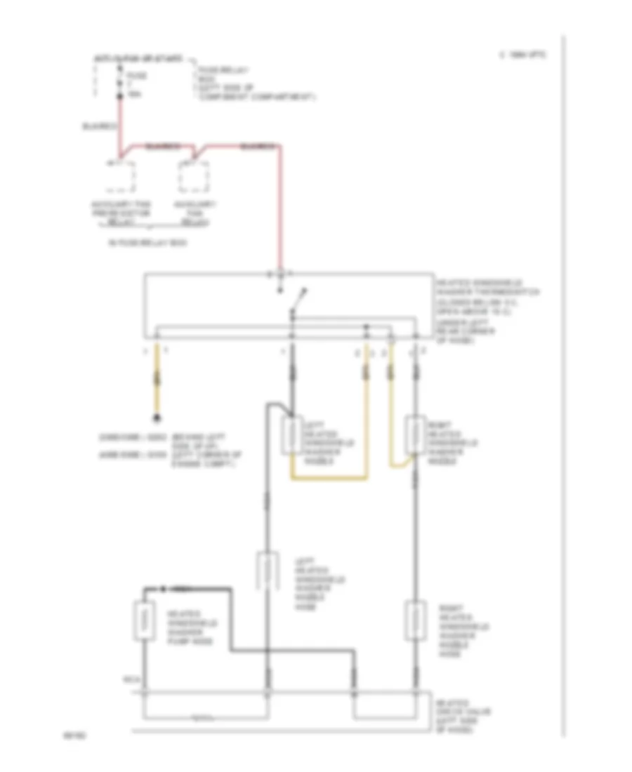
Heated Windshield Washer Wiring Diagram for Mercedes-Benz 500E 1993
List of elements for Heated Windshield Washer Wiring Diagram for Mercedes-Benz 500E 1993:
- (300d/300e)
- (400e/500e)
- (behind left side of i/p) (left corner of engine compt)
- (closed below 5 c, open above 15 c)
- (under left rear corner of hood)
- 1994 vftc c
- Auxiliary fan preresistor relay
- Auxiliary fan relay
- Fuse 16a
- Fuse/relay box (left side of component compartment)
- G100
- G202
- Heated check valve (left side of hood)
- Heated windshield washer pump hose
- Heated windshield washer thermoswitch
- Hot in run or start
- In fuse/relay box
- Left heated windshield washer nozzle
- Left heated windshield washer nozzle hose
- Nca
- Right heated windshield washer nozzle
- Right heated windshield washer nozzle hose

 Čeština
 Dansk
Dansk Deutsch
 English
 English
 Español
 Suomi
Suomi Français
 Français
 עברית
עברית Hrvatski
 Magyar
 Italiano
 日本語
日本語 한국어
한국어 Nederlands
 Polski
 Português
 Português
 Română
 Русский
 Slovenčina
 Slovenščina
 Svenska
 Türkçe
 中文 (中国)