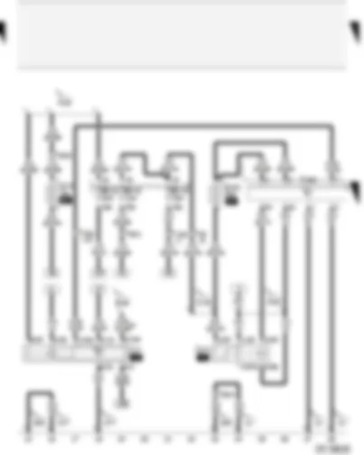
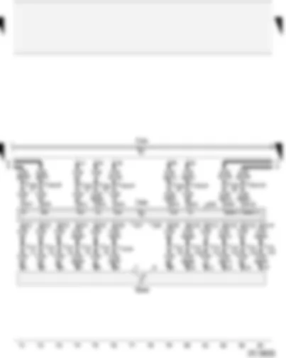
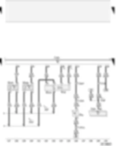
| A | Battery |
| B | Starter |
| C | Alternator |
| D | Ignition/starter switch |
| S88 | Strip fuse |
| SB20 | Fuse -20- on fuse box |
| SB30 | Fuse -30- on fuse box |
| SB31 | Fuse -31- on fuse box |
| SB38 | Fuse -38- on fuse box |
| T6f | 6-pin connector, green, in footwell, front left |
| T17e | 17-pin connector, blue, in footwell, front left |
| 65 | Earth point, left longitudinal member, rear, between B and C pillar |
| 500 | Screw connection -1- (30), on relay plate |
| A2 | Positive (+) connection (15), in dash panel wiring harness |
| A32 | Positive (+) connection (30), in dash panel wiring harness |
| A98 | Positive (+) connection -4- (30), in dash panel wiring harness |
| B177 | Connection (61), in interior wiring harness |
| P2 | Positive (+) connection (30), in battery wiring harness |
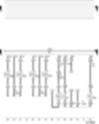
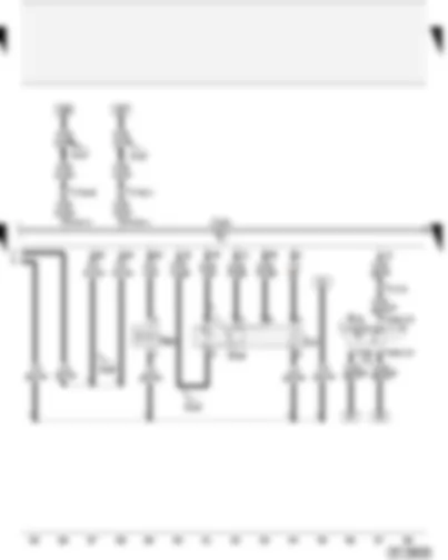
| J17 | Fuel pump relay |
| J220 | Motronic control unit |
| J271 | Motronic current supply relay |
| S74 | Air mass meter fuse |
| S102 | Engine control unit fuse |
| SB18 | Fuse -18- on fuse box |
| SB19 | Fuse -19- on fuse box |
| SB45 | Fuse -45- on fuse box |
| T6f | 6-pin connector, green, in footwell, front left |
| T10s | 10-pin connector, white, in footwell, front left |
| 12 | Earth point, in engine compartment, left |
| 277 | Earth connection -3-, in interior wiring harness |
| 284 | Earth connection -6-, in interior wiring harness |
| A100 | Connection -2- (87), in dash panel wiring harness |
| B155 | Connection -2- (TK (door contact)), in interior wiring harness |
| D50 | Positive (+) connection (30), in engine compartment wiring harness |
| D78 | Positive (+) connection -1- (30a), in engine compartment wiring harness |
| * | ⇒ Applicable Current Flow Diagram: Convenience systems |
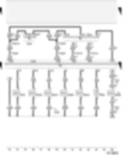
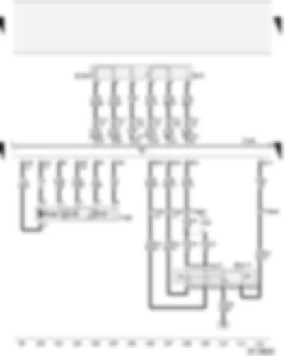
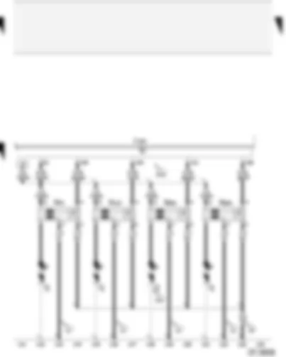
| F | Brake light switch |
| F36 | Clutch pedal switch |
| J220 | Motronic control unit |
| N30 | Injector, cylinder 1 |
| N31 | Injector, cylinder 2 |
| N32 | Injector, cylinder 3 |
| N33 | Injector, cylinder 4 |
| T17 | 17-pin connector, brown, in footwell, front left |
| T17e | 17-pin connector, blue, in footwell, front left |
| B131 | Connection (54), in interior wiring harness |
| B149 | Positive (+) connection -2- (15a), in interior wiring harness |
| D95 | Connection (injectors), in engine compartment wiring harness |
| D137 | Connection -2- (injectors), in engine compartment wiring harness |
| * | Only applies to models with cruise control system |
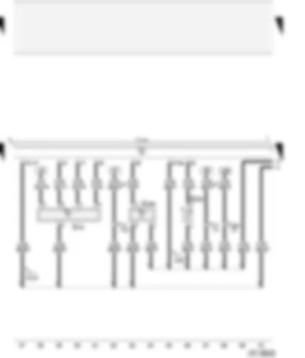
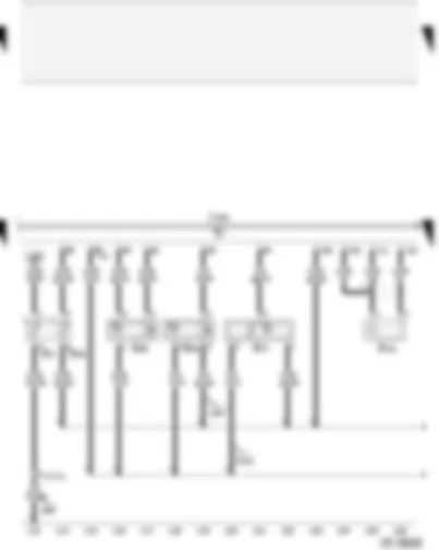
| E87 | Air conditioning system/Climatronic operating and display unit |
| F265 | Map-controlled engine cooling thermostat |
| J220 | Motronic control unit |
| J293 | Radiator fan control unit |
| N79 | Heater element (crankcase breather) |
| N205 | Inlet camshaft timing adjustment valve -1- |
| N276 | Fuel pressure regulating valve |
| N280 | Air conditioning system compressor regulating valve |
| N290 | Fuel metering valve |
| N316 | Intake manifold flap air flow control valve |
| T6g | 6-pin connector, black, on radiator fan control unit |
| T10e | 10-pin connector, brown, connector point, A pillar, left |
| T10s | 10-pin connector, white, in footwell, front left |
| T17e | 17-pin connector, blue, in footwell, front left |
| D104 | Positive (+) connection -2- (30a), in engine compartment wiring harness |
| * | Only applies to models with air conditioner |
| G70 | Air mass meter |
| G235 | Exhaust gas temperature sender -1- |
| G294 | Brake servo pressure sensor |
| J220 | Motronic control unit |
| T10s | 10-pin connector, white, in footwell, front left |
| T17 | 17-pin connector, brown, in footwell, front left |
| 316 | Earth connection (sender earth -2-), in engine wiring harness |
| D174 | Connection -2- (5V), in engine wiring harness |
| * | Only applies to models without air conditioner |
| E16 | Heater/heat output switch |
| G39 | Lambda probe |
| J220 | Motronic control unit |
| N80 | Activated charcoal filter system solenoid valve 1 (pulsed) |
| T16h | 16-pin connector, black, on heater controls |
| T17 | 17-pin connector, brown, in footwell, front left |
| T17e | 17-pin connector, blue, in footwell, front left |
| Z19 | Lambda probe heater |
| A121 | Connection (high bus), in dash panel wiring harness |
| A122 | Connection (low bus), in dash panel wiring harness |
| D144 | Positive (+) connection -5- (30), in engine compartment wiring harness |
| D169 | Connection (NOx), in engine compartment wiring harness |
| * | Only applies to models without air conditioner |
| E45 | Cruise control system switch |
| G79 | Accelerator pedal position sender |
| G185 | Accelerator pedal position sender -2- |
| G186 | Throttle valve drive (electric power control) |
| G187 | Throttle valve drive angle sender -1- (electric power control) |
| G188 | Throttle valve drive angle sender -2- (electric power control) |
| J220 | Motronic control unit |
| J338 | Throttle valve module |
| T10n | 10-pin connector, black, behind steering column switch trim |
| T10s | 10-pin connector, white, in footwell, front left |
| T17 | 17-pin connector, brown, in footwell, front left |
| A16 | Connection (cruise control system), in dash panel wiring harness |
| * | Only applies to models with cruise control system |
| G2 | Coolant temperature sender |
| G28 | Engine speed sender |
| G40 | Hall sender |
| G61 | Knock sensor I |
| G62 | Coolant temperature sender |
| G71 | Intake manifold pressure sender |
| J220 | Motronic control unit |
| T17 | 17-pin connector, brown, in footwell, front left |
| 220 | Earth connection (sender earth), in engine wiring harness |
| 269 | Earth connection (sender earth) -1-, in dash panel wiring harness |
| D141 | Connection (5V), in engine wiring harness |
| F51 | Thermo-switch for coolant circulation |
| G212 | Exhaust gas recirculation potentiometer |
| G247 | Fuel pressure sender |
| G336 | Intake manifold flap potentiometer |
| J220 | Motronic control unit |
| J234 | Airbag control unit |
| N18 | Exhaust gas recirculation valve |
| T10s | 10-pin connector, white, in footwell, front left |
| T17 | 17-pin connector, brown, in footwell, front left |
| T17f | 17-pin connector, white, connector point, A pillar, left |
| 220 | Earth connection (sender earth), in engine wiring harness |
| A125 | Connection (crash signal), in dash panel wiring harness |
| D141 | Connection (5V), in engine wiring harness |
| J220 | Motronic control unit |
| N70 | Ignition coil 1 with output stage |
| N127 | Ignition coil 2 with output stage |
| N291 | Ignition coil 3 with output stage |
| N292 | Ignition coil 4 with output stage |
| P | Spark plug connector |
| Q | Spark plugs |
| 12 | Earth point, in engine compartment, left |
| 19 | Earth point, near ignition coil |
| 221 | Earth connection (engine earth), in engine wiring harness |
| D51 | Positive (+) connection -1- (15), in engine compartment wiring harness |
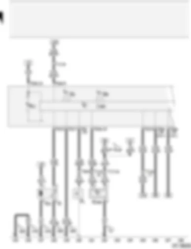
| F1 | Oil pressure switch |
| G | Fuel gauge sender |
| G1 | Fuel gauge |
| G6 | Fuel pump (pre-supply pump) |
| G9 | Oil temperature gauge |
| G266 | Oil level/oil temperature sender |
| J285 | Control unit with display in dash panel insert |
| K2 | Alternator warning lamp |
| T6f | 6-pin connector, green, in footwell, front left |
| T17 | 17-pin connector, brown, in footwell, front left |
| T17e | 17-pin connector, blue, in footwell, front left |
| T32 | 32-pin connector, blue, on dash panel insert |
| T32a | 32-pin connector, green, on dash panel insert |
| 12 | Earth point, in engine compartment, left |
| 269 | Earth connection (sender earth) -1-, in dash panel wiring harness |
| 279 | Earth connection -5-, in interior wiring harness |
| 284 | Earth connection -6-, in interior wiring harness |
| B135 | Connection -1- (15a), in interior wiring harness |
| * | Only applies to models with air conditioner |

 Deutsch
 English
 English
 Español
 Français
 Nederlands
 Русский

