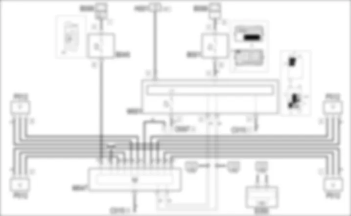

Wiring diagram - TYRE INFLATION PRESSURE CONTROL SYSTEM - Fiat GRANDE PUNTO 1.4 16v
Components - TYRE INFLATION PRESSURE CONTROL SYSTEM - Fiat GRANDE PUNTO 1.4 16v
| Component code | Description | Reference to the assembly |
| B001 | JUNCTION UNIT | |
| B045 | LUGGAGE COMPARTMENT JUNCTION UNIT (CVB) | |
| B099 | MAXI FUSE BOX ON BATTERY | |
| C015 | DASHBOARD EARTH, DRIVER'S SIDE | - |
| D097 | SHORT CIRCUITING COUPLING | - |
| E050 | INSTRUMENT PANEL | |
| H001 | IGNITION SWITCH | |
| M001 | BODY COMPUTER | |
| M047 | TYRE INFLATION PRESSURE CONTROL UNIT | |
| P012 | TYRE PRESSURE CONTROL UNIT ANTENNA | front:rear: |
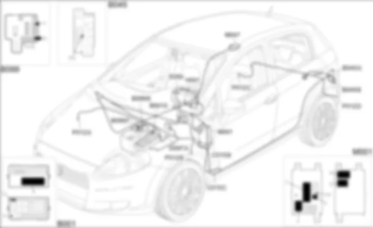
Component location - TYRE INFLATION PRESSURE CONTROL SYSTEM - Fiat GRANDE PUNTO 1.4 16v
| Component code | Description | Reference to the assembly |
| B001 | JUNCTION UNIT | |
| B045 | LUGGAGE COMPARTMENT JUNCTION UNIT (CVB) | |
| B099 | MAXI FUSE BOX ON BATTERY | |
| C015 | DASHBOARD EARTH, DRIVER'S SIDE | - |
| D097 | SHORT CIRCUITING COUPLING | - |
| E050 | INSTRUMENT PANEL | |
| H001 | IGNITION SWITCH | |
| M001 | BODY COMPUTER | |
| M047 | TYRE INFLATION PRESSURE CONTROL UNIT | |
| P012 | TYRE PRESSURE CONTROL UNIT ANTENNA | front:rear: |
Description - TYRE INFLATION PRESSURE CONTROL SYSTEM - Fiat GRANDE PUNTO 1.4 16v
The system referred to as the TPMS "Tyre Pressure Monitoring System" monitors tyre pressure and temperature moment by moment. It sends the required information via the CAN network. In particular, it activates on the instrument panel a low pressure signal for one or more tyres or a puncture signal for one tyre. It consists of a reception signal located inside the passenger compartment (in the boot on the right hand side) and four transmission sensors located inside the tyre on the rim that send signals to four reception aerials.The aerials acquire information on the status of the four tyres via radio signals. They then communicate with the tyre pressure control unit, which communicates with the Body Computer via the CAN.At key-on, the control unit conducts an initial check: when the vehicle moves, the sensors measure the pressure and then make a transmission to indicate the initial status. The receiver receives this transmission from all the sensors within 5 seconds so that it can check tyre function.Two intervention thresholds are identified that are stored inside the receiver. The first (defined as CHECK) indicates that one or more tyres are at a pressure slightly lower than optimum pressure and the user should therefore check and restore the correct value. The second threshold (defined as WARNING) is set to indicate a constant or sudden pressure loss due to a puncture in one or more tyres.For more details:The control unit supply lines are protected by fuses in the boot compartment control unit and Body Computer.
Operational description - TYRE INFLATION PRESSURE CONTROL SYSTEM - Fiat GRANDE PUNTO 1.4 16v
Control unit M47 is supplied at pin 1 directly from the battery from a line protected by fuse F62 of boot compartment control unit B45 .The ignition-controlled power supply (INT) arrives at pin 16 from the line protected by fuse F61 of Body Computer M1.The control unit is earthed at pin 10.Pin 8 of M47 is the origin for the CAN line connected to Body Computer M1:Body Computer M1 - connector G - is supplied directly from the battery from a line protected by maxifuse F2 of engine compartment control unit B1. It is ignition-operated (INT) at pin 32 of connector D. Pin 10 of connector H of M1 supplies a reference earth to the Body Computer.The four receivers of sensors P12 receive a 5V supply from pin 2 of M47 and a reference earth from pins 12, 13, 14 and 15 ; they send a pressure signal to pins 3, 4, 5 and 6 of M47.
 Deutsch
 English
 English
 Español
 Français
 Nederlands
 Русский


