ELECTRONIC MUFFLER
Electronic Muffler Wiring Diagram for Chevrolet Corvette Stingray 2014
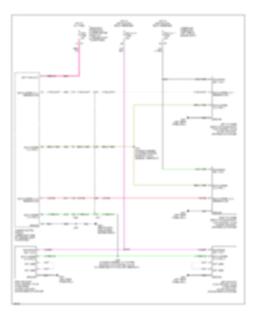
List of elements for Electronic Muffler Wiring Diagram for Chevrolet Corvette Stingray 2014:
- Batt pos volt
- Chassis control module (under right side of luggage compt floor panel)
- Exh flapper vlv 1 feedback sig
- Exh flapper vlv 2 feedback sig
- Exh flapper vlv ctrl 1
- Exh flapper vlv ctrl 2
- Exh vlv 1 fuse 20a
- Exh vlv 2 fuse 20a
- G401 (left rear wheelwell)
- G404 (behind right side of rear bumper fascia)
- Ground
- Hot at all times
- Hot w/ ignition main relay energized
- Iccm fuse 15a
- J341
- J343
- J344 (chassis harness, 10 cm from control solenoid valve assembly breakout)
- J345 (chassis harness, 31.4 cm from exhaust flow control valve, cylinder deactivation left breakout)
- J400
- Left cylinder deactivation exhaust flow control valve (in left exhaust, upstream of muffler)
- Left exhaust flow control valve (if equipped) (in left exhaust, downstream of muffler)
- Not used
- Rear body fuse block (under center front of luggage compt floor panel)
- Right cylinder deactivation exhaust flow control valve (in right exhaust, upstream of muffler)
- Right exhaust flow control valve (if equipped) (in right exhaust, downstream of muffler)
- Run/crank ign 1 volt
- Underhood fuse block (left side of engine compt)
- X311
- X350
- X5 k2
 English