ELECTRONIC POWER STEERING
Electronic Power Steering Wiring Diagram for Acura ILX 2013
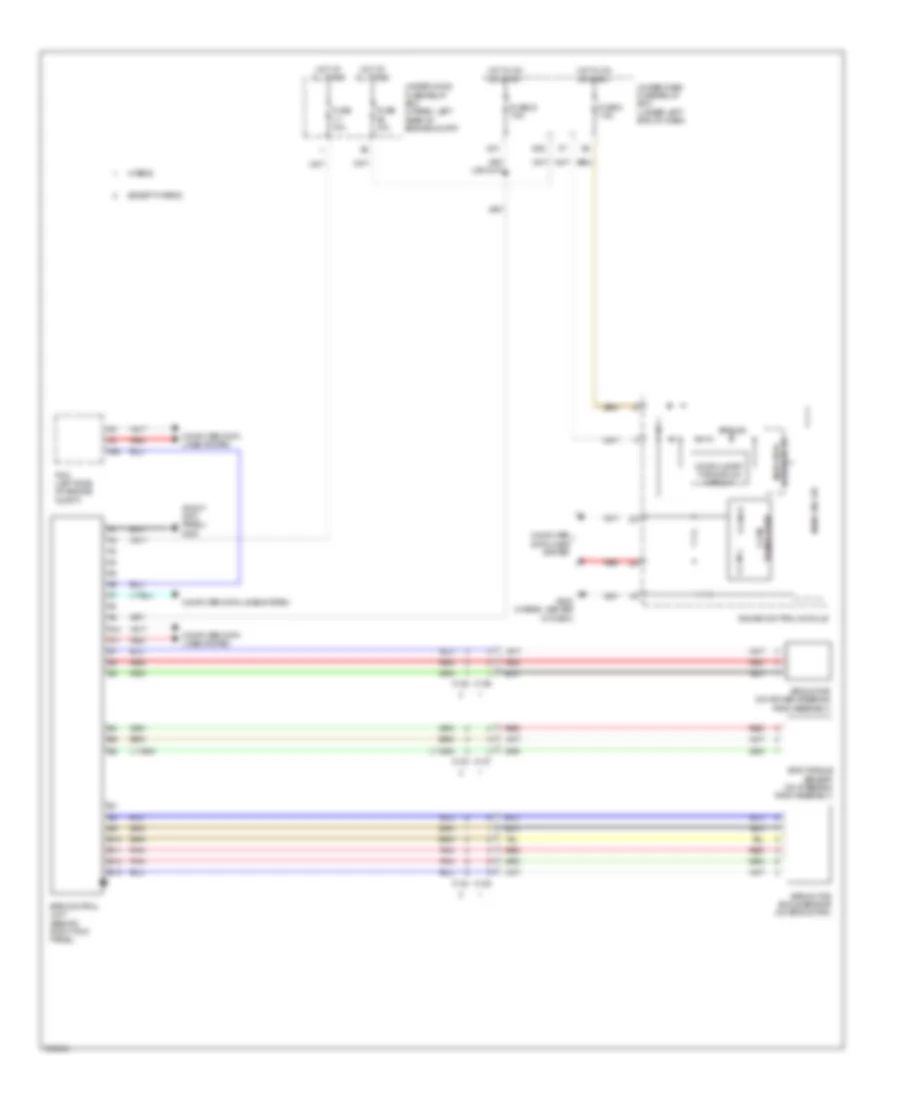
List of elements for Electronic Power Steering Wiring Diagram for Acura ILX 2013:
- (right kick panel) g403
- A10
- A11
- A22
- B10
- B11
- B12
- B13
- C122
- C123
- C124
- C126
- C127
- C128
- Compulsory turning-on circuit
- Computer data lines system
- D28
- D31
- Drive circuit indicator
- Eps control unit (behind right kick panel)
- Eps ind
- Eps motor (on power steering rack assembly)
- Eps motor angle sensor (on eps motor)
- Eps torque sensor (on steering rack assembly)
- Except hybrid
- F-can h
- F-can l
- Fuse 1-1 70a
- Fuse 10a
- Fuse 24 7.5a
- Fuse 5 7.5a
- G502 (hybrid: center of dash)
- Gauge control module
- Hot at all times
- Hot in on or start
- Hybrid
- Main circuit
- Pcm (left side of engine compt)
- Pnk
- Red
- Transceiver f-can
- Under-dash fuse/relay box (under left end of dash)
- Under-hood fuse/relay box (hybrid: left rear of engine compt)
 English