ELECTRONIC POWER STEERING
Electronic Power Steering Wiring Diagram for Acura MDX 2014
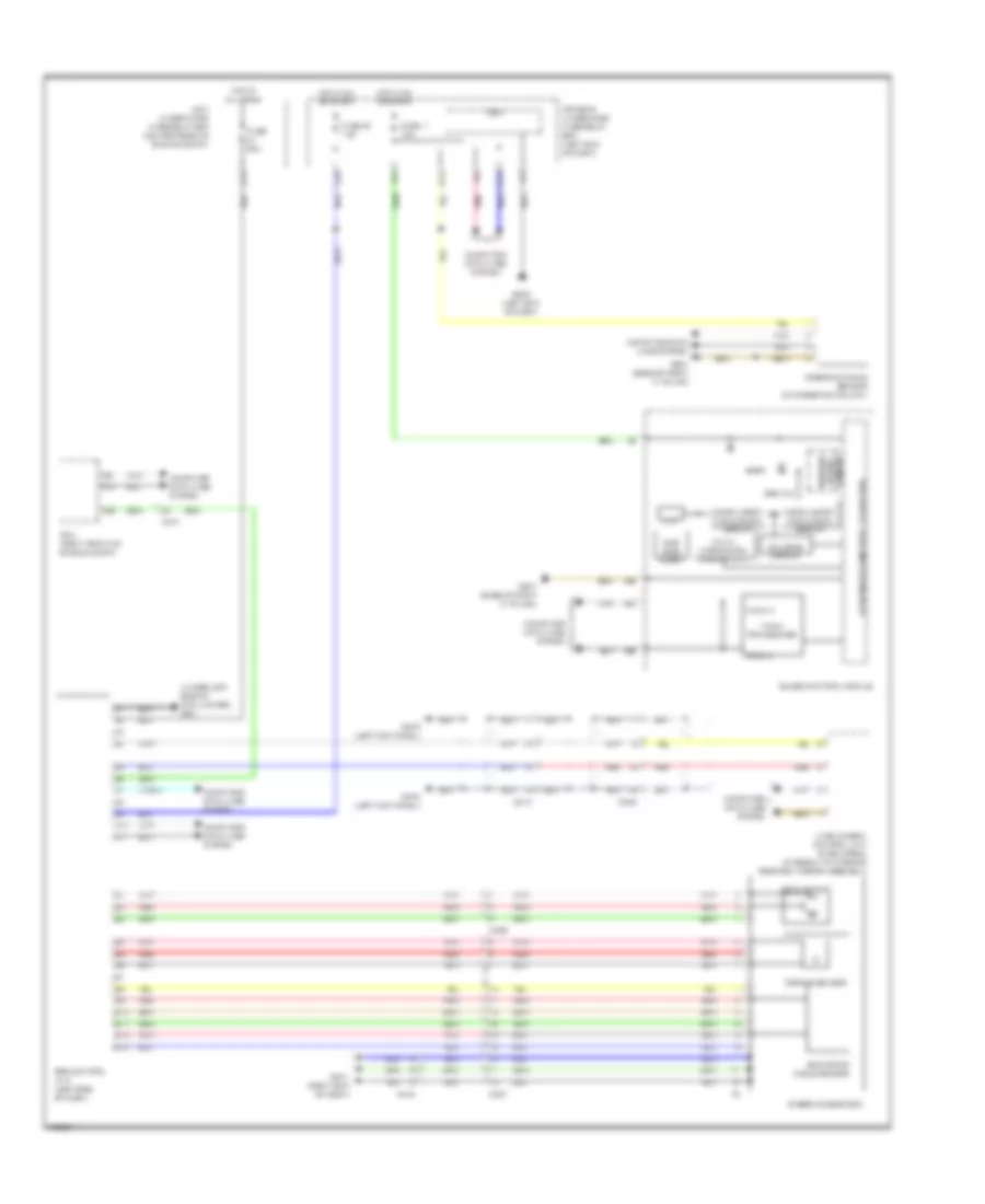
List of elements for Electronic Power Steering Wiring Diagram for Acura MDX 2014:
- (under left side of cowl cover) g401
- 3.3v
- 32-bit microcomputer + flash rom
- 8mb/ 32mb flash
- A10
- A11
- A12
- A27
- A28
- A32
- A40
- B10
- B11
- B12
- B13
- C213
- C222
- C226
- C227
- C407
- C416
- Circuit driver warning
- Compulsory turning-off circuit
- Compulsory turning-on circuit
- Computer data lines system
- Driver's under-dash fuse/relay box (left end of dash)
- Eps control unit (left side of dash)
- Eps ind
- Eps motor
- Eps motor angle sensor
- F-can h
- F-can l
- F-can transceiver
- F29
- Fail-safe circuit
- Fuse 11 7.5a
- Fuse 2-1 60a
- Fuse 23 7.5a
- G15
- G301 (right end of dash)
- G402 (left kick panel)
- G502 (left end of dash)
- G507 (base of right "a" pillar)
- Gauge control module
- H10
- Hot at all times
- Hot in on or start
- Lkas camera/ control unit (if equipped) (integral to interior rearview mirror assembly)
- Main under-hood fuse/relay box (center rear of engine compt)
- Micu
- Multi- information display (tft)
- Pcm (right front of engine compt)
- Pnk
- Red
- Steering angle sensor (on steering column)
- Steering gear box
- Torque sensor
 English