ELECTRONIC POWER STEERING
Electronic Power Steering Wiring Diagram for Chevrolet Astro 1998
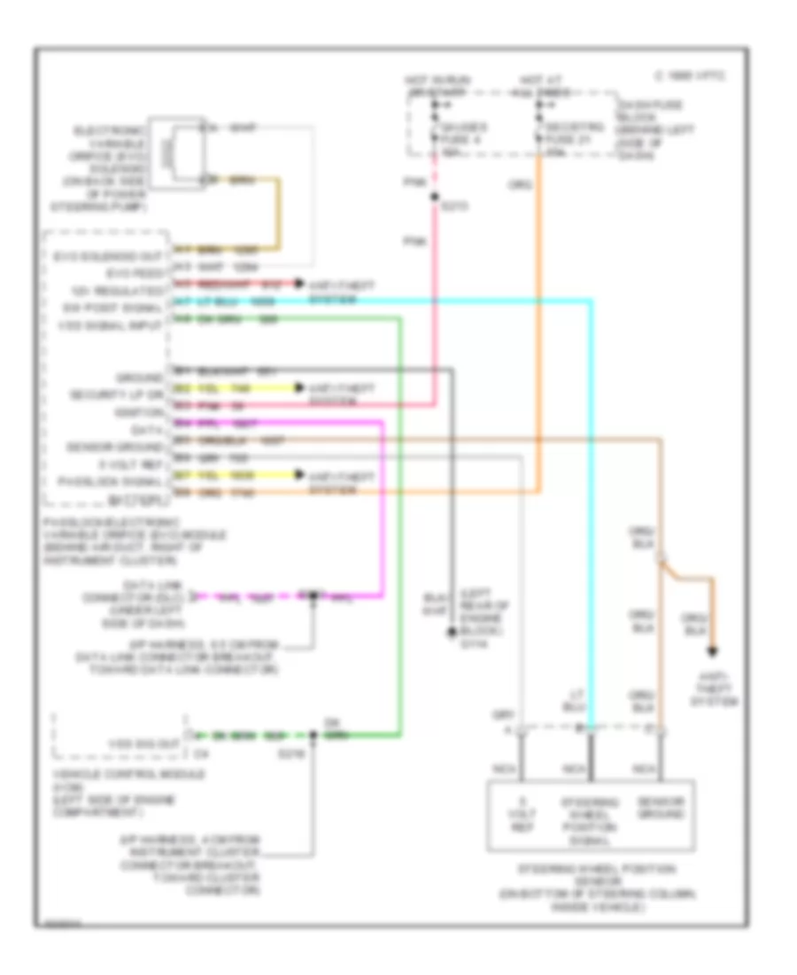
List of elements for Electronic Power Steering Wiring Diagram for Chevrolet Astro 1998:
- (i/p harness, 4 cm from instrument cluster connector breakout, toward cluster connector)
- (i/p harness, 6.5 cm from data link connector breakout, toward data link connector)
- 12v regulated
- 1995 vftc c
- 5 volt ref
- Anti- theft system
- Anti-theft system
- Battery
- Dash fuse block (behind left side of dash)
- Data
- Data link connector (dlc) (under left side of dash)
- Electronic variable orifice (evo) solenoid (on back side of power steering pump)
- Evo feed
- Evo solenoid out
- Gauges fuse 4 10a
- Ground
- Hot at all times
- Hot in run or start
- Ignition
- Nca
- Passlock signal
- Passlock/electronic variable orifice (evo) module (behind air duct, right of instrument cluster)
- Pnk
- Rear of engine block) g114
- S213
- S218
- S233
- Sec/strg fuse 21 10a
- Security lp dr
- Sensor ground
- Steering wheel position sensor (on bottom of steering column, inside vehicle)
- Steering wheel position signal
- Sw posit signal
- Vehicle control module (vcm) (left side of engine compartment)
- Volt ref
- Vss sig out
- Vss signal input
 English