
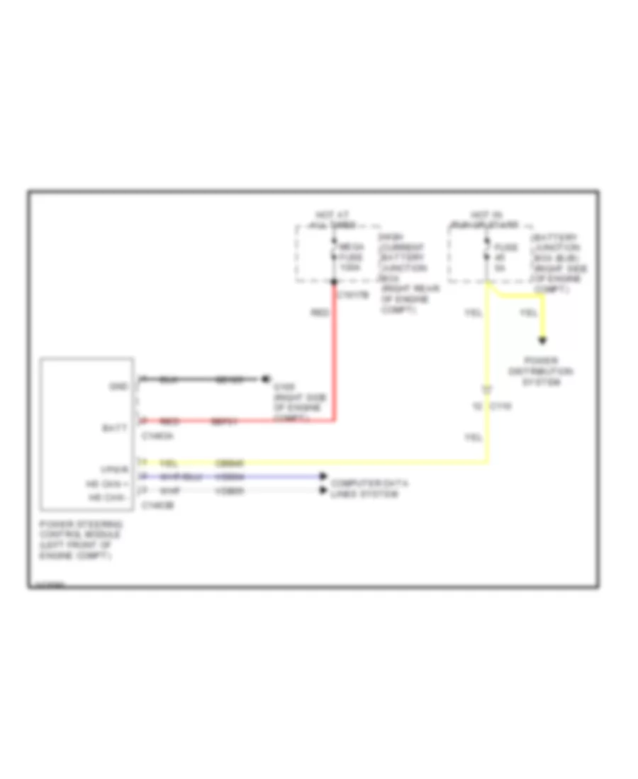
ELECTRONIC POWER STEERING
Electronic Power Steering Wiring Diagram for Ford Mustang Shelby GT500 2011
List of elements for Electronic Power Steering Wiring Diagram for Ford Mustang Shelby GT500 2011:
AIR CONDITIONINGANTI-THEFTCRUISE CONTROLCOOLING FANBODY CONTROL MODULESDEFOGGERSCOMPUTER DATA LINESANTI-LOCK BRAKESELECTRONIC POWER STEERINGEXTERIOR LIGHTSINTERIOR LIGHTSPOWER DISTRIBUTIONINSTRUMENT CLUSTERENGINE PERFORMANCEHORNGROUND DISTRIBUTIONNAVIGATIONPOWER SEATSPOWER MIRRORSHEADLIGHTSRADIOSHIFT INTERLOCKPOWER DOOR LOCKSPOWER TOP/SUNROOFTRANSMISSIONPOWER WINDOWSSTARTING/CHARGINGWARNING SYSTEMSSUPPLEMENTAL RESTRAINTSWIPER/WASHERTRUNK, TAILGATE, FUEL DOOR