
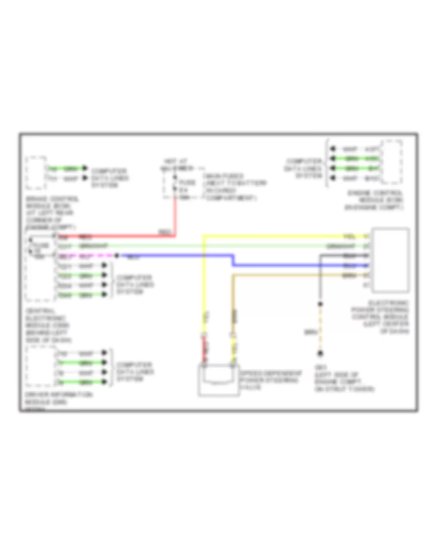
ELECTRONIC POWER STEERING
Electronic Power Steering Wiring Diagram for Volvo XC90 R-Design 2009
List of elements for Electronic Power Steering Wiring Diagram for Volvo XC90 R-Design 2009:
ANTI-LOCK BRAKESANTI-THEFTAIR CONDITIONINGCOMPUTER DATA LINESCRUISE CONTROLBODY CONTROL MODULESDEFOGGERSCOOLING FANEXTERIOR LIGHTSELECTRONIC POWER STEERINGHEADLIGHTSGROUND DISTRIBUTIONENGINE PERFORMANCEINSTRUMENT CLUSTERHORNINTERIOR LIGHTSMEMORY SYSTEMSPOWER WINDOWSPOWER DISTRIBUTIONNAVIGATIONRADIOSHIFT INTERLOCKPOWER TOP/SUNROOFPOWER SEATSPOWER DOOR LOCKSSUPPLEMENTAL RESTRAINTSTRANSMISSIONSTARTING/CHARGINGWARNING SYSTEMSWIPER/WASHER